
User's Manual

Ripwave Base Station I&C Guide Navini Networks, Inc.
104 Part #40-00047-00 Rev D v1.0
February 28, 2003
Test Procedure
Follow the steps in the procedure below.
Step 1. Ensure that system calibration has been successfully performed.
Step 2. Enter the value for receive sensitivity (line 23) into the Base Station Calibration
Verification Form. It is located in the EMS Configuration & Alarm Manager (CAM)
GUI by selecting the BTS, then selecting air interface > layer 1 > show
configuration. Select the General tab.
Step 3. Enter the value for the test cable loss (line 24) into the Base Station Calibration
Verification Form. Test cable loss has to be measured before testing begins. If a test
cable is not used, enter zero for test cable loss in the Base Station Calibration
Verification Form.
Step 4. Enter the values for the antenna cable loss and RFS sweeps (measured) into the Base
Station Calibration Verification Form under cable loss (lines 40 to 48) and insertion
loss through cal cable and RFS (lines 54 to 69). The values are obtained from the RFS
System Test Form.
Step 5. Record the DAC words for RX gain from EMS Layer 1 data into the Base Station
Calibration Verification Form (lines 90 to 97). It is located in the EMS Configuration
& Alarm Manager by selecting the BTS, then select air interface > layer 1 >
show configuration. Select the Antenna tab.
Step 6. Set the Output power of the Signal Generator equal to the
RF Power injected at the cal
cable to get sensitivity at the antenna (line 25) of the Base Station Calibration
Verification Form. Ensure that the spreadsheet has calculated the value by pressing F9
to calculate.
Step 7. Confirm that all CPE’s are turned off. Enter the command “ebCamShow” at the BTS
console to check for packets being transferred. Run the command two or three times to
validate that packet numbers are not changing.
Step 8. Set the power switch on the BTS to “OFF”.
Step 9. Remove the CHP-A board from the BTS chassis.
Step 10. Install the CHP test board into the CHP-A slot in the BTS chassis.
Step 11. Set the power switch on the BTS to “ON”.
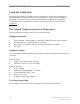
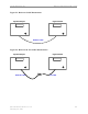
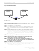
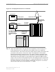
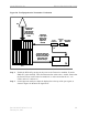
Step 12. Set up the test equipment as shown in Figure 56.