
User's Manual

Navini Networks, Inc. Ripwave Base Station I&C Guide
Part #40-00047-00 Rev D v1.0 105
February 28, 2003
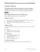
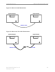
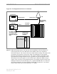
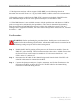
Figure 56: Test Equipment for Receive Verification
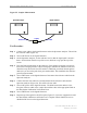
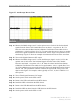
Step 13. Adjust the Oscilloscope to view only the receive timeframe, as shown in Figure 57.
Center the quietest area of one RX frame in the middle of the screen. Adjust the
horizontal sweep for 100 to 200 us/division to obtain the best reading. This ensures that
you measure only the noise of the receive frame. The amplitude for each channel
should be approximately 200 mV/division. This setting is arbitrary depending on the
environment. The setting should be as low as possible, and you should still be able to
differentiate between the signals. Set the Oscilloscope to display the RMS (average)
voltage of the waveform. If the equipment permits, also display the peak-to-peak value.
Setting the channel on the Oscilloscope to AC, coupled with BW limit “on”, limits the
noise being measured to less than 20 MHz in bandwidth. The objective is to measure
only the noise within the receiver bandwidth (5 - 6 MHz).
Calibration cable
To the TDD SYNC
connector on the
back of the BTS
(if enabled)
To test points
on CHP card
RFS
Oscilloscope
Ext. Trigger on the rear
of the scope, If available.
Or use Channel 2 input
and select it as the trigger
source.
Channel 1
Signal Generator
8 RF cables from
the RFS connected
to the BTS
Test Cable (optional)
BTS
Test Points on
CHP Test Board
D
B
C
A
Test Points on
CHP Test Board
D
B
C
A