
User's Manual

Ripwave Base Station I&C Guide Navini Networks, Inc.
106 Part #40-00047-00 Rev D v1.0
February 28, 2003
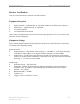
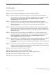
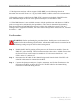
Figure 57: Oscilloscope Receive Time
Step 14. Measure the RMS voltage (in mV) in the quietest area of each of the four baseband
signals from the front of the Channel Processor test board – test points A, B, C, D.
Enter the values into the Base Station Calibration Verification Form under receiver
performance - noise level (lines 76 to 79). To ensure that there are no surges or random
interference signals included in the measurement, use the single sweep function on the
Oscilloscope. Figure 57 shows an example of unwanted noise bursts in the waveform.
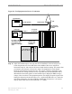
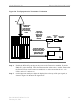
Step 15. Turn on the Signal Generator’s RF output.
Step 16. Measure the RMS voltage (in mV) on the Oscilloscope (signal + noise, S+N) in the
quietest area of each of the four baseband signals from the front of the Channel
Processor test board – test points A, B, C, D. Enter the values into the Base Station
Calibration Verification Form under receiver performance - noise + signal (lines 76 to
79). If the calibration was successful, then all of the levels should be between 180 and
240 mV rms. The spreadsheet will then calculate the signal, SNR, noise power, and
relative noise figure. For example, values typically are -102, 10, and 3.5 dB for a 2.6
GHz system.
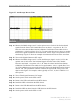
Step 17. Turn off the Signal Generator’s RF output.
Step 18. Set the power switch on the BTS to OFF.
Step 19. Remove the CHP test board from the BTS chassis.
Step 20. Install the CHP-A board into the BTS chassis.
Step 21. Remove the CHP-B board from the BTS chassis.
Step 22. Install the CHP test board into the CHP-B slot in the BTS chassis.
Step 23. Set the power switch on the BTS to “ON”.