
User's Manual

Ripwave Base Station I&C Guide Navini Networks, Inc.
108 Part #40-00047-00 Rev D v1.0
February 28, 2003
* If the Spectrum Analyzer will not support 5 MHz RBW, use the following formula to
determine the correction factor: 10 * log10 (5 MHz /RBW). Add this value to the measurements.
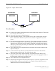
**If possible, connect a cable from the TDD SYNC connector on the back of the BTS to the
EXT TRIGGER input on the rear of the Spectrum Analyzer. Set the TRIG to EXT.
***If the RMS detector is not available, measure with the peak detector and subtract 9.5 dB for
peak to average ratio (calculated by the spreadsheet). This value is determined by measuring
both the peak detected and RMS detected power values, then taking the average of the two
readings. Due to equipment variations, this value will not always be the same; however, it should
be within +/- 1 dB.
Test Procedure
WARNING! Before performing the procedure below, disable power to the transceiver
modules before disconnecting any RF cables. All antenna cables must be connected to the
BTS during testing except for the one that is being tested.
Step 1. Disable the RF shelf by turning off the power to the Transceiver modules. From the
EMS GUI, select the BTS. Then from the menu bar select action > disable. Ensure that
the Power LED on each Transceiver module is off. Also ensure that the A1 – A8
LED’s on the CC card are off.
Step 2. Disconnect the RF cable for the channel being tested from the back of the BTS. All
other RF cables must be connected to the BTS.
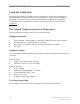
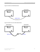
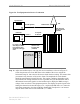
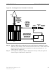
Step 3. Connect the Spectrum Analyzer, Coupler, Attenuator, and 50 ohm Terminator to the
RF input on the BTS, as shown in Figure 58. The RF cable for the channel being
tested is not connected during the test.