
User's Manual

Navini Networks, Inc. Ripwave Base Station I&C Guide
Part #40-00047-00 Rev D v1.0 109
February 28, 2003
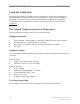
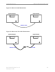
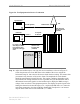
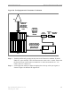
Figure 58: Test Equipment for Transmitter Verification
Step 4. Enable the RF shelf by turning on the power to the Transceiver modules. From the
EMS GUI, select the BTS. Then from the menu bar select action > enable. Ensure that
the Power LED on each Transceiver module is on. Also ensure that the A1 – A8
LED’s on the CC card are on.
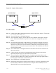
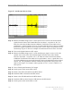
Step 5. On the Spectrum Analyzer, adjust the display line to the top of the sync signal, as
shown in Figure 59. Measure the signal level.
Connect the
Coupler input
directly to the
BTS antenna
output to be
measured
RFS
Coupler
(20dB min)
Attenuator
30dB
25W
5W 50 ohm
Terminator
Coupled
port
All cables from
the RFS are
connected to the
BTS except for
the channel being
tested
Spectrum Analyzer
BTS
Connect the TDD Sync
connector on the back of
the BTS to the External
Trigger input on the
Spectrum Analyzer
Connect the
Coupler input
directly to the
BTS antenna
output to be
measured
Connect the
Coupler input
directly to the
BTS antenna
output to be
measured
RFS
Coupler
(20dB min)
Attenuator
30dB
25W
5W 50 ohm
Terminator
5W 50 ohm
Terminator
Coupled
port
All cables from
the RFS are
connected to the
BTS except for
the channel being
tested
All cables from
the RFS are
connected to the
BTS except for
the channel being
tested
Spectrum Analyzer
BTS
Connect the TDD Sync
connector on the back of
the BTS to the External
Trigger input on the
Spectrum Analyzer
Connect the TDD Sync
connector on the back of
the BTS to the External
Trigger input on the
Spectrum Analyzer