
User's Manual

Ripwave Base Station I&C Guide Navini Networks, Inc.
110 Part #40-00047-00 Rev D v1.0
February 28, 2003
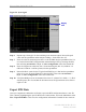
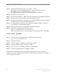
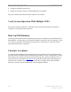
Figure 59: Sync Signal
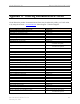
Step 6. Repeat steps 1 through 5 for the remaining seven antenna outputs. Record the peak
value into the spreadsheet under analyzer readings – Peak (lines 90 to 97).
Step 7. Enter the value for antenna power that is set in the EMS into the spreadsheet (line 30).
It is located in the EMS Configuration & Alarm Manager GUI by selecting the BTS,
then selecting air interface > layer 1 > show configuration. Select the General tab.
Step 8. Enter the Coupler/test cable loss (line 31) and antenna gain (line 32) (8 dBi for 2.4
GHz and 17 dBi for 2.6 GHz systems) into the spreadsheet.
Step 9. Record the DAC words for the TX gain from EMS Layer 1 data into the spreadsheet
(lines 93 to 100). From the EMS GUI, select the BTS. Then select air interface >
layer 1 > show configuration. Select the Antenna tab.
Step 10. Verify that RMS power at the antenna (lines 90 to 97, column G) is within +/- 1 dB of
antenna power (line 30) and that the deviation across all eight antennas is less than or
equal to 3 dB.
Export BTS Data
Once you complete the calibration verification, export the BTS configuration data to a text file.
This is done by highlighting the specific BTS in the CAM window, and on the Main Menu select
File > Export BTS Data. This saves the configuration information if needed for later retrieval.
Display
Line
Display
Line