
User's Manual

Ripwave Base Station I&C Guide Navini Networks, Inc.
112 Part #40-00047-00 Rev D v1.0
February 28, 2003
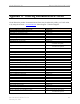
Equipment Settings
Part of the Test Procedures below.
Test Procedure Setup
Set up the test procedures, per the following.
Step 1. Calibrate and sanity check the BTS.
Step 2. Connect the CPE and the attenuators. The combined attenuation should be set roughly
as follows:
Total attenuation = PTX - 30 + 18 - Cal cable loss + 80
Where PTX is the Tx output power at antenna input port that is set in EMS during
calibration. Cal cable loss is the loss of the calibration cable.
The total attenuation should be partitioned between fixed and adjustable attenuators in
such a way that the adjustable attenuator is set to about 10dB.
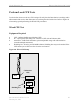
Step 3. Disconnect the calibration cable from the back of the BTS shelf and connect it to the
attenuator as shown in the drawing
Step 4. Ping the BTS continuously from the CPE.
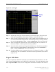
Step 5. Check the sync level at the CPE debug tool. The level should be about -80dBm.
Test Procedure - Check CPE Sensitivity & Output Power
Follow the steps in the procedure below.
Step 1. Record the downlink TCC power level and SNR reading on the CPE debug tool.
Step 2. Calculate the effective noise floor: NF= SNR
TCC
- Level
TCC
.
Where SNR
TCC
is the TCC SNR and Level
TCC
is the received downlink TCC level.
NF should be close to -127 ±5.
Step 3. Check CPE output power cap difference. It should be greater than 0.
Step 4. Increase the attenuation by 10dB (increase the attenuation of the adjustable attenuator).
Step 5. Measure the effective noise floor and the output power cap difference gain.
Step 6. Increase the attenuation by another 10dB and take the measurements again (if the link
is broken when the attenuation increases 10dB, back off the attenuation by 10dB and
then increase the attenuation with 1dB steps until the link is broken. Then reduce the
attenuation by 4dB).