
User's Manual

Navini Networks, Inc. Ripwave Base Station I&C Guide
Part #40-00047-00 Rev D v1.0 113
February 28, 2003
Step 7. Calculate the maximum path allowed as follows:
Max loss = Attenuation total + Cal cable loss + 30
Where Attenuation total is the total attenuation of all attenuators (fixed + adjustable).
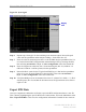
Test Procedure - Check BTS Sensitivity (Individual Antenna)
Step 1. Set the attenuation of the attenuator so the total attenuation is about
P
TX
- 30 - Cal cable loss +80.
Step 2. Activate antenna #1 only.
Step 3. Record the uplink TCC power level and SNR reading on the BTS debug tool.
Step 4. Calculate the effective noise floor: NF= SNR
TCC
- Level
TCC
.
Where SNR
TCC
is the TCC SNR and Level
TCC
is the received downlink TCC level.
NF should be close to: SNR - BTS Sensitivity + 25 ±5.
Where BTS sensitivity is the BTS sensitivity setting during calibration.
Step 5. Record the CPE output power.
Step 6. Increase the attenuation by 10dB (increase the attenuation of the adjustable attenuator).
Step 7. Measure BTS effective noise floor and CPE output power again.
Step 8. Increase the attenuation by another 10dB and take the measurements again (if the link
is broken when the attenuation increases 10dB, back off the attenuation by 10dB and
then increase the attenuation with 1dB steps until the link is broken. Then reduce the
attenuation by 4dB. The same attenuation will be used for all antenna tests).
Step 9. Calculate the maximum path allowed as follows:
Max loss = Attenuation total + Cal cable loss + 30
Where Attenuation total is the total attenuation of all attenuators (fixed + adjustable).
Step 10. Repeat the steps for antennas 2 through 8.
Step 11. Average the CPE output power over antennas 1~8 for each attenuation setting.
Test Procedure - Check BTS Sensitivity (Antenna Array)
Step 1. Set the initial attenuation the same as in the individual antenna testing procedure.
Step 2. Activate all antennas.
Step 3. Record the uplink TCC power level and SNR reading on BTS debug tool.