
User's Manual

Navini Networks, Inc. Ripwave Base Station I&C Guide
Part #40-00047-00 Rev D v1.0 133
February 28, 2003
Appendix C: RFS System Test (Cable Sweeps)
Introduction
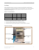
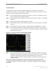
Before installing a Base Station at a site, the RFS and the associated cables must be tested, and
the results of the tests documented. The tests verify the performance of three major components:
the data/power cable, the RF cables, and the RFS unit. This procedure includes, as well, the full
RFS sub-assembly with the associated cables. All results for the RFS and cable testing are
recorded in the RFS System Test Form, P/N 40-00093-00.
Procedures
RFS Data/Power Cable
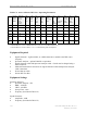
This test will check the integrity of the data/power cable. The cable being tested consists of six
twisted pairs of conductors. The conductors will be tested for continuity, opens, and shorts. Male
connectors are on both ends of the cable. Each connector is wired the same. You will need to
check all cables – the main cable from the RFS to the data/power cable surge protector, and the
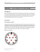
jumper cable from the data/power cable surge protector to the BTS. The pin layout is shown in
Figure C1, looking at the connector face. Table C1 provides the pinout details.
Figure C1: Pin Layout
A
B
C
D
E
F
G
H
J
K
L
M