
User's Manual


Ripwave Base Station I&C Guide Navini Networks, Inc.
134 Part #40-00047-00 Rev D v1.0
February 28, 2003
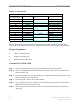
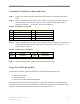
Table C1: Pinout Details
Perform the continuity test with both the Volt Ohm Meter (VOM) and the power/data cable
tester. If the power/data cable tester is not available, perform the continuity test with the VOM.
Required Equipment
• VOM – Continuity tester
• Jumper for shorting pins
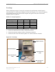
• RFS power/data cable tester
Continuity Test With VOM
Step 1. On one end of the cable, short a pair of conductors using a shorting device.
Step 2. Using a VOM/Digital Volt Meter (DVM) set to ohms, verify a short is present on the
pair at the other end.
Step 3. Leaving one probe on one of the paired pins, contact all of the other pins with the other
probe, ensuring an open connection.
Step 4. Check all 6 pairs of wires in the same manner.
Step 5. Verify continuity from the connector case to the drain wire (pin D) on each end of the
cable and between each connector case.
Step 6. Verify an open circuit from the connector case to each individual wire, except to the
drain wire.
Wire Color Wire Color Signal Name
RED PAIR +12V A
BLACK +12V A RTN
BROWN Heater
DRAIN GND (Shield Wire)
BLACK PAIR RX_EN_B-
WHITE RX_EN_B+
BLUE PAIR RX_EN_A+
BLACK RX_EN_A-
BLACK PAIR Diagbus-
GREEN Diagbus+
BLACK PAIR +12V B Return
YELLOW +12V B
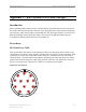
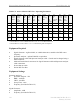
POWER CABLE PIN OUT
A
B
C
D
Circular
Connector(s)
J
K
L
M
E
F
G
H