
User's Manual

Navini Networks, Inc. Ripwave Base Station I&C Guide
Part #40-00047-00 Rev D v1.0 135
February 28, 2003
Continuity Test With Power/Data Cable Tester
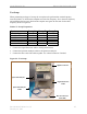
Step 1. Connect one end of the power/data cable to the connector on the power/data cable
tester.
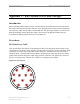
Step 2. Using a VOM/DVM set to ohms, check resistance to ground on the other end of the
cable. Resistance is checked from the case of the connector to the individual pin.
Resistance readings (+/- 10 percent ) are shown in Table C2.
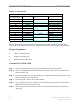
Table C2: Resistance to Ground
Pin Resistance Pin Resistance
A 1K ohms G 6.2K ohms
B 2K ohms H 8.2K ohms
E 3.3K ohms L 10K ohms
F 5.1K ohms M 12K ohms
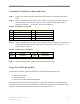
Step 3. Using a VOM/DVM set to ohms, check resistance between the pairs on the other end
of the cable. Resistance should be the sum of the resistance of the two pairs, +/- 10
percent. Refer to Table C3.
Table C3: Resistance of Two Pairs
Pins Resistance Pins Resistance
A & B 3K ohms G & H 14.4K ohms
E & F 8.4K ohms L & M 22K ohms
Step 4. Remove the power/data cable tester from the power/data cable.
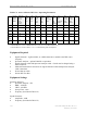
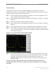
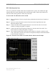
Sweep Test of RF Cables & RFS
Sweep testing of the RF cables and the RFS is performed in three separate steps.
• Sweep of the cables
• Sweep of the RFS
• Sweep of the cables and the RFS together
All results will be entered in the RFS System Test Form, P/N 40-00093-00. The total of the
insertion loss for the cables and the RFS will be equal to the insertion loss of both parts swept
together. The minimum and maximum cable loss are listed in Table C4.