
User's Manual

Ripwave Base Station I&C Guide Navini Networks, Inc.
136 Part #40-00047-00 Rev D v1.0
February 28, 2003
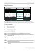
Table C4: Active & Passive RFS Loss / Operating Parameters
PA Max
Output
Power
[dBm]
BTS Max
Output
power
with
*Filter
[dBm]
CAL
Cable
Min
Loss
CAL
Cable
Max
Loss
RF
Cable
Min
Loss
[dB]
Active
RFS
Loss
Typ
[dB]
Passive
RFS
Loss Typ
[dB]
TX
Pwr
to
Ant
Min
[dBm]
TX
Pwr
to
Ant Max
[dBm]
RX
Power
to Ant
Min
[dBm]
RX
Power
to Ant
Max
[dBm]
Notes
2.3 +38 +37 3.0 6.0 0 3.2 1.7 20 35 -95 -75
2.4 +37 N/A 4.0 9.5 0 3.2 1.7 10 25 -85 -65 -05
SYN
2.4 +37 N/A 3.0 4.5 0 3.2 1.7 18 30 -95 -70 -01
SYN
2.5 +39 +38 3.0 6.0 0 3.2 1.7 20 35 -95 -75
2.6
EF
GH
+39 +38 3.0 6.0 0 3.2 1.7 20 35 -95 -75
2.6
EF
+37 +35 3.0 4.5 0 3.2 1.7 20 35 -95 -75 -05
SYN
* Channel filter for 2.5/2.6 or Block Filter for 2.3 has 1.0 +/- 0.2 dB Insertion Loss
* Channel filter for 2.6 EF Combo is 1.8 +/- 0.2 dB including cable to backplane.
Equipment Required
• Signal Generator - Agilent 8648C, or suitable alternative, tunable to the RFS center
frequency
• Spectrum Analyzer - Agilent E4402B, or equivalent
• Signal Generator cable and Spectrum Analyzer cable – Gender can be changed using a
barrel connector
• Male and Female barrel connectors for Signal Generator cable and Spectrum Analyzer
cable connections
• Power/data test cable
• Navini RFS Test Box
Equipment Settings
Spectrum Analyzer:
• Spectrum Analyzer - 5M
• RBW - 100 KHz
• VBW - 100 KHz
• Sweep Time - Auto
• Frequency (Provided in Table C5)
Signal Generator:
• Amplitude - 0 dB
• Frequency (Provided in Table C5)