
User's Manual

Navini Networks, Inc. Ripwave Base Station I&C Guide
Part #40-00047-00 Rev D v1.0 137
February 28, 2003
Test Setup
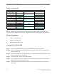
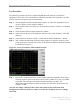
When performing each type of sweep, the sweep has to be performed at certain frequency
intervals (Table C5). Perform the complete test at the first frequency. Go to the next frequency
and recalibrate the test setup. Perform the complete test again. Do the same for the third
frequency. Refer to Figure C2.
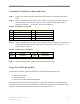
Table C5: Sweep Frequencies
System Sweep 1 Sweep 2 Sweep 3
2.3 GHz High band
2348.25 2352.50 2357.50
2.3 GHz Low band
2307.50 2312.50 2316.75
2.4 GHz
2400.00 2440.00 2473.50
2.5 GHz
2500.00 2548.00 2596.00
2.6 GHz
2602.00 2620.00 2641.00
2.6 GHz EFGH
2602.00 2641.00 2683.00
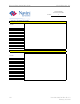
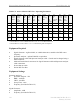
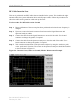
1. Connect the Signal Generator cable to the Signal Generator.
2. Connect the Spectrum Analyzer cable to the Spectrum Analyzer.
3. Connect the other end of the cables together. Use a barrel connector if needed.
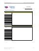
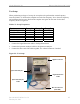
Figure C2: Test Setup
Spectrum Analyzer
Signal Generator
Barrel Connector
(if needed)
Signal Generator
Cable
Spectrum Analyzer
Cable
Spectrum Analyzer
Signal Generator
Barrel Connector
(if needed)
Signal Generator
Cable
Spectrum Analyzer
Cable