
User's Manual


Ripwave Base Station I&C Guide Navini Networks, Inc.
138 Part #40-00047-00 Rev D v1.0
February 28, 2003
Test Procedure
The following procedures are for the Agilent E4402B Spectrum Analyzer. If alternative
equipment is used, refer to the manufacturer’s calibration procedures. The key point is to make
accurate microwave frequency power measurements.
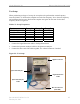
Step 1. Turn the Signal Generator and Spectrum Analyzer on. Allow the equipment to warm
up for 15 minutes for the output to stabilize.
Step 2. Set the Signal Generator frequency to the desired test frequency (Table C5) of the RFS
under test.
Step 3. Set the Signal Generator output amplitude to 0 dBm.
Step 4. Set the center frequency of the Spectrum Analyzer to the center frequency of the RFS
under test.
Step 5. Set the Spectrum Analyzer to Span = 5 MHz and Resolution Bandwidth = 100kHz.
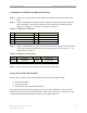
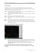
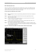
Step 6. Take a marker measurement on the Spectrum Analyzer by using the ‘marker to peak’
or the ‘peak search’ function. The screen on the Spectrum Analyzer should look similar
to that shown in Figure C3.
Figure C3: Sweep Test Marker Measurement Example
Step 7. If the marker measurement doesn’t read 0.0 dBm, adjust the amplitude on the Signal
Generator until the Spectrum Analyzer marker reads 0.0 dBm, or as close to 0.0 dBm
as possible. This will remove all losses associated with the test cables. All
measurement data should be recorded one digit to the right of the decimal point. For
example, 31.5dB.
Once the test setup is calibrated, these cables will remain in place and will be used
throughout the whole test. If the test cables are removed or changed, incorrect readings
will result.