
User's Manual


Navini Networks, Inc. Ripwave Base Station I&C Guide
Part #40-00047-00 Rev D v1.0 139
February 28, 2003
RF Cable Insertion Loss
This test is performed on all RF cables that are installed in the system. This includes the eight
antenna cables, the system calibration cable, and all jumper cables. Follow the procedures for
either the cables on the ground or cables run up the tower.
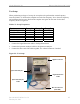
Test Procedure For RF Cables on the Ground
Step 1. Ensure calibration of the test setup has been performed each time the test frequency is
changed.
Step 2. If present, remove the barrel connector from between the Signal Generator and
Spectrum Analyzer cables.
Step 3. Connect the cable from the Signal Generator to one end of the cable. Use a barrel
connector to change the gender, if required.
Step 4. Connect the cable from the Spectrum Analyzer to the other end of the cable. Use a
barrel connector to change the gender, if required.
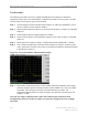
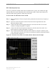
Step 5. Take a marker measurement on the Spectrum Analyzer by using the ‘marker to peak’
or the ‘peak search’ function. The screen on the Spectrum Analyzer should look similar
to the one shown in Figure C4.
Figure C4: Insertion Loss (Cables on Ground) Marker Measurement Example