
User's Manual

Navini Networks, Inc. Ripwave Base Station I&C Guide
Part #40-00047-00 Rev D v1.0 141
February 28, 2003
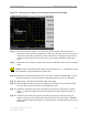
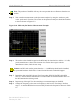
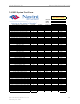
Figure C5: Insertion Loss (Cables on Tower) Marker Measurement Example
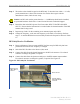
Step 8. The result should be within +/- 0.5 dB of the calculated value. If the insertion loss
results do not agree with the manufacturer’s data, check the cable connectors for proper
connection to the cable, and check for kinks in the cable. If the Spectrum Analyzer has
a distance to fault (DTF) function, this can be used to help troubleshoot kinks in the
cable.
Step 9. Divide this value in half and assign the result to the calibration cable and to the antenna
cable.
Caution: Cables with results greater than the specified limits (i.e., 2 or 3 dB high) should
not be installed, as a potential hardware fault exists.
Step 10. Record the data in the RFS System Test Form under “MAIN FEEDER LOSS”. Ensure
that the information is recorded under the channel number that is on the cable label.
Step 11. Repeat steps 3 through 10 for antenna cables 2 through 8.
Step 12. When finished, take the average of the eight values obtained for the calibration cable.
Use this value for the insertion loss of the calibration cable.
Step 13. Change the frequency to the next test frequency (refer back to Test Setup). Perform
steps 1 – 12 until all cables have been successfully tested at the frequencies given in
Table C5.
Step 14. Check the value of the nine jumpers at all three frequencies, per the procedure for
cables on the ground. Record the data in the RFS System Test Form under “JUMPER
LOSS”. Ensure that the information is recorded under the channel number that is on the
cable label.