
User's Manual
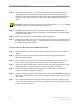

Ripwave Base Station I&C Guide Navini Networks, Inc.
142 Part #40-00047-00 Rev D v1.0
February 28, 2003
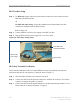
RFS Test Box Setup
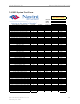
Step 1. For RFS only testing, connect the power/data test cable to the data connector on the
RFS and to the RFS Test Box.
OR
For RFS and cable testing, connect the installation power/data cable to the data
connector on the RFS and to the RFS Test Box.
Refer to Figure C6.
Step 2. Connect the RFS Test Box power supply to the RFS Test Box.
Step 3. Plug the RFS Test Box power supply into a 110 VAC outlet.
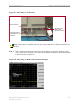
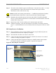
Figure C6: RFS Only Testing Setup
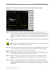
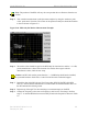
RFS Only Transmit Verification
Ensure that the calibration of the test setup and RFS Test Box setup for RFS Only has been
performed each time the test frequency is changed. Refer to Figure C7.
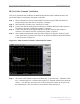
Step 1. Switch the RFS Test Box to the transmit (Tx) mode.
Step 2. Connect the cable from the Spectrum Analyzer to the RFS cal connector. Use a barrel
connector to change the gender, if required.
Step 3. Connect the cable from the Signal Generator to the RFS antenna input number 1. Use a
barrel connector to change the gender, if required.
Power/Data cable
connected to the RFS
RFS Test Box
RFS Test Box
power supply
Power/Data cable
connected to the RFS
RFS Test Box
RFS Test Box
power supply