
User's Manual
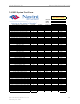

Navini Networks, Inc. Ripwave Base Station I&C Guide
Part #40-00047-00 Rev D v1.0 143
February 28, 2003
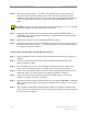
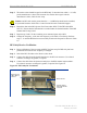
Figure C7: RFS Only Tx Verification
Note: The position of the RFS will vary the sweep results due to reflections from the test
surface.
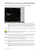
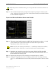
Step 4. Take a marker measurement on the Spectrum Analyzer by using the ‘marker to peak’
or the ‘peak search’ function. The screen on the Spectrum Analyzer should look similar
to the one shown in Figure C8.
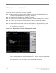
Figure C8: RFS Only Tx Marker Measurement Example
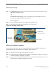
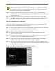
Barrel connector
Signal Generator
cable to RFS
antenna 1 connector
Spectrum Analyzer
cable to RFS cal
connector
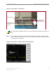
Barrel connector
Signal Generator
cable to RFS
antenna 1 connector
Spectrum Analyzer
cable to RFS cal
connector