
User's Manual

Ripwave Base Station I&C Guide Navini Networks, Inc.
146 Part #40-00047-00 Rev D v1.0
February 28, 2003
RFS & Cables Transmit Verification
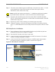
This test is performed after the RFS is installed and the antenna cables, calibration cable, and
power/data cable are connected to the inputs on the RFS.
Step 1. Ensure calibration of the test setup and RFS Test Box setup for RFS and cables has
been performed each time the test frequency is changed.
Step 2. Switch the RFS Test Box to the Transmit (Tx) mode.
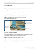
Step 3. Connect the cable from the Spectrum Analyzer to the RFS calibration cable connector.
Use a barrel connector to change the gender, if required.
Step 4. Connect the cable from the Signal Generator to the RFS antenna cable number 1
connector. Use a barrel connector to change the gender, if required.
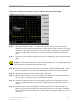
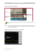
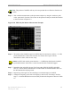
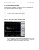
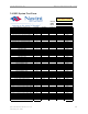
Step 5. Take a marker measurement on the Spectrum Analyzer by using the ‘marker to peak’
or the ‘peak search’ function. The screen on the Spectrum Analyzer should look similar
to the one shown in Figure C11.
Figure C11: RFS & Cables Tx Marker Measurement Example
Step 6. The marker value should be equal to the RFS Only Tx insertion loss + calibration cable
loss + antenna cable loss + antenna cable jumper loss. Transmit insertion loss should be
within +/- 2.0 dB of the sum of the parts. If the insertion loss results do not agree with
the manufacturer’s data, check the test setup and the cable connections.