
User's Manual

Ripwave Base Station I&C Guide Navini Networks, Inc.
148 Part #40-00047-00 Rev D v1.0
February 28, 2003
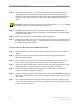
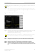
Step 7. The marker value should be equal to the RFS Only RX Insertion Loss + Calibration
Cable Loss + Antenna Cable Loss + Antenna Cable Jumper Loss. RX Insertion Loss
should be within +/- 2.0 dB of the sum of the parts. If the Insertion Loss results do not
agree with the manufacturers data, check the test setup and the cable connections.
Caution: If RFS & cables test results are greater than the +/- 2.0 dB limits, they should
not be installed on a tower, as a potential hardware fault exists. Verify connections and
contact Navini Networks Technical Support.
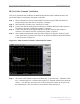
Step 8. Record the data in the RFS System Test Form under “TOTAL RX PATH LOSS
(CABLE-RFS)”. Ensure that the information is recorded under the channel number that
is on the cable label.
Step 9. Repeat steps 5 through 8 for the remaining seven antenna cable inputs on the RFS.
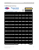
Step 10. Change the frequency to the next test frequency (refer to Test Setup). Perform steps 1-9
until the RFS has been successfully tested at the frequencies given in Table C5.