Ripwave Base Station ™ Installation & Commissioning Guide Part Number 40-00047-00 Revision D, Version 1.0 February 28, 2003 Proprietary All information disclosed by this document is the proprietary property of Navini Networks, Inc. and is protected by copyright, trademark, and/or trade secret laws. All rights therein are expressly reserved.
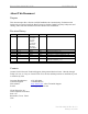
Ripwave Base Station I&C Guide Navini Networks, Inc. About This Document Purpose This document provides a Navini-certified Installation & Commissioning Technician with instructions to properly install the Base Transceiver Station, Radio Frequency Subsystem, and cabling; and to test and commission the Base Station after installation. Revision History Date 2001 Revision/Version A/1.0 Editors N/A Comments Draft B/v1.0 C/1.0 C/1.0 C/1.0 C/1.0 D/1.0 Authors J. Price C. Keltner A. Chua P. Blain J.
Navini Networks, Inc. Ripwave Base Station I&C Guide Permissions, Trademarks & Distribution Copyright© February 2003, Navini Networks, Inc. All information contained herein and disclosed by this document is the proprietary property of Navini Networks, Inc. and all rights therein are expressly reserved. Acceptance of this material signifies agreement by the recipient that the information contained in this document is confidential and that it will be used solely for the purposes set forth herein.
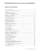
Ripwave Base Station I&C Guide Navini Networks, Inc. TABLE OF CONTENTS ABOUT THIS DOCUMENT .............................................................................................................. 2 PERMISSIONS, TRADEMARKS & DISTRIBUTION ............................................................................ 3 SAFETY ........................................................................................................................................ 6 REGULATORY INFORMATION....................
Navini Networks, Inc. Ripwave Base Station I&C Guide APPENDIX A: ORDERING DOCUMENTATION & FORMS ......................................... 119 APPENDIX B: SITE CANDIDATE EVALUATION FORM.............................................. 121 APPENDIX C: RFS SYSTEM TEST (CABLE SWEEPS) .................................................. 133 APPENDIX D: BASE STATION INSTALLATION CERTIFICATION .......................... 151 APPENDIX E: CONFIGURATION FORMS...............................................................
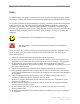
Ripwave Base Station I&C Guide Navini Networks, Inc. Safety To optimize safety and expedite installation and service, read this document thoroughly. Follow all warnings, cautions, and instructions marked on the equipment and included in this document. To aid in the prevention of injury and damage to property, cautionary symbols have been placed in this document to alert the reader to known potentially hazardous situations, or hazards to equipment or procedures.
Navini Networks, Inc. Ripwave Base Station I&C Guide 11. Do not disassemble the equipment. Removing covers exposes dangerous voltages or other risks and also voids the warranty. Incorrect reassembly can cause equipment damage or electrical shock. Only an authorized repair technician should service this product. 12. Do not expose the equipment to extreme hot or cold temperatures. 13. Do not use the equipment under the following conditions: • When the equipment has been exposed to water or moisture.
Ripwave Base Station I&C Guide Navini Networks, Inc. Regulatory Information FCC Notice WARNING! This device is a Radio Frequency transmitter. It is required to comply with FCC RF exposure requirements for transmitting devices. A minimum separation distance of 8 inches (20 cm) or more must be maintained between the antenna and all persons during device operations to ensure compliance with the FCC’s rules for Radio Frequency Exposure.
Navini Networks, Inc. Ripwave Base Station I&C Guide Battery Caution & Procedures WARNING! To reduce risk of injury or fire, follow these instructions when handling the battery. 1. Risk of explosion is possible if the battery is replaced with one not supplied by Navini Networks. 2. Do not dispose of the battery in a fire. It may explode. Check with the local codes for battery disposal guidelines. 3. Do not open or mutilate the battery.
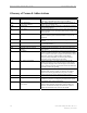
Ripwave Base Station I&C Guide Navini Networks, Inc. Glossary of Terms & Abbreviations Term 802.11 Stands For.... 802.
Navini Networks, Inc. Term CD CDMA CD-ROM CHP CLEC CLI CORBA CPE dB dBd dBi DHCP DiffServ DIR DL DNS DS-1 DSL Ripwave Base Station I&C Guide Stands For.... Meaning Compact Disk or 2Change Directory 1An optical disk capable of storing large amounts of data (700x floppy disk). It can be inserted into most pc’s and “read” to load files onto a computer 2A software programming term in “C” language that tells the computer to go to a different location in the computer’s memory.
Ripwave Base Station I&C Guide Term DSP Stands For....
Navini Networks, Inc. Term L1 Stands For.... Layer 1 L2 Layer 2 L3 Layer 3 LAN Local Area Network LCP Link Control Protocol LED Light-emitting Diode LLC Logical Link Controller LOS Line-of-sight MAC Media Access Control Mb MB Mbps MDM Megabit Megabyte Megabits Per Second Modem Card MHz Megahertz MIB Management Information Base MMDS NE Multipoint Multi-channel Distribution Service 1 Near-end or 2Network Element NLOS Non Line-of-site Part #40-00047-00 Rev D v1.
Ripwave Base Station I&C Guide Term NMS NOC OAM OS OSI PC PCB PDU Ping PPPoE Propagation PSK PSN PSTN QAM QoS 14 Navini Networks, Inc. Stands For.... Network Management System Meaning A product that helps manage a network generally hosted on a well-equipped computer such as an engineering workstation. The system tracks network statistics and resources.
Navini Networks, Inc. Term RAM RF RFS RSSI Rx S-CDMA SMDS SMS SNMP SNR SO/HO SSI SW SYN SYNCH TCC TCP TCP/IP Ripwave Base Station I&C Guide Stands For.... Random Access Memory Radio Frequency Meaning Computer memory that can be accessed randomly. A portion of the electromagnetic spectrum in the frequency range between audio and infrared: 100 KHz to 20 GHz. RF measurements are expressed in Hz (unit for measuring frequency); MHz = 1 Million Hz; GHz = 1 Billing Hz.
Ripwave Base Station I&C Guide Term TDD Stands For.... Time Division Duplex TFFS True Flash File System TTL Time-to-live Tx Transmit UL UpLink USB Universal Serial Bus VCC Virtual Channel Circuit VCI Virtual Channel Identifier VCL Vector Virtual Channel Link Vector VPC Virtual Private Channel VP Virtual Path VPI Virtual Path Identifier VPL Virtual Path Link WAN 1 2 16 Wide Area Network or Wireless Access Network Navini Networks, Inc.
Navini Networks, Inc. Ripwave Base Station I&C Guide Chapter 1: Overview Ripwave Description A Ripwave system has three main components: the Customer Premise Equipment (CPE); the Base Station; and the Element Management System (EMS). The Base Station performs the CPE registration and call processing, and provides the interface between the backhaul network and the EMS. It is made up of the Base Transceiver Station (BTS) and the Radio Frequency Subsystem (RFS) (Figure 1).
Ripwave Base Station I&C Guide Navini Networks, Inc. Procedural Documents & Forms You will refer to other Ripwave documents, procedures, and forms in the process of installing and commissioning the Base Station. They are listed in Appendix A of this manual. The product documentation is provided on the Ripwave Standard Documentation CD (Table 1). As well, the EMS manuals can be viewed on-line through the EMS Server and Client applications.
Navini Networks, Inc. Ripwave Base Station I&C Guide I&C Process Flowchart To put the I&C activities in the context of overall system deployment, Figure 2 provides a ‘flow’ of the key activities that are performed prior to and during the installation and commissioning of the Ripwave Base Station. Post-I&C, the system that has been installed and commissioned goes through Acceptance Testing against the customer’s objectives for that site.
Ripwave Base Station I&C Guide Navini Networks, Inc. Figure 2: I&C Process Flowchart Site Engineering 1-Complete Project Plan for customer 2-Generate coverage prediction map 3-Conduct site survey & complete the Site Candidate Evaluation Form. Complete the Interference Analysis/CPE Site Survey Tool.
Navini Networks, Inc. Ripwave Base Station I&C Guide Figure 2: I&C Process Flowchart, cont’d. Installation 1-From shipping containers received at customer site, gather Manufacturing’s inventory sheet & test data collected from the BTS & RFS equipment shipped. Verify all equipment arrived, the test data is available, & serial numbers match paperwork. Keep as part of customer site records. 2-Install all system buss bars & surge protectors 3-Install & sweep RF cables. Record results on RFS System Test Form.
Ripwave Base Station I&C Guide Navini Networks, Inc. Figure 2: I&C Process Flowchart, cont’d. A 9-Install & verify DC input power source to BTS 10-Install GPS antennas 11-Sweep the RFS. Record the results and the RFS serial numbers on the RFS System Test Form. 12-Install RFS & surge protectors. Connect 9 RF cables & data/power cable to the RFS. 13-Sweep installed RFS & cables to verify connections & cable loss. Record results on RFS System Test Form.
Navini Networks, Inc. Ripwave Base Station I&C Guide Figure 2: I&C Process Flowchart, cont’d. B 17-Provide printed package of measured results & equipment inventory to customer on-site. 18-Go over results using forms &` get customer sign-off on Installation using Base Station Site Installation Form. End Part #40-00047-00 Rev D v1.
Ripwave Base Station I&C Guide Navini Networks, Inc. Figure 2: I&C Process Flowchart, cont’d. Commissioning 1-Review customer network plans (i.e., T1 vs. Ethernet) 2-Are you using No 3a-Install & configure* the Test the customer EMS Server & Client. Connect EMS Server to the BTS. ? Yes 3b-Install & configure* the customer EMS Server & Client. Connect to the BTS. *Appendix E: Configuration Data Forms 4-Enter the RFS configuration by running the RFS script that shipped with the antenna eqpt.
Navini Networks, Inc. Ripwave Base Station I&C Guide Figure 2: I&C Process Flowchart, cont’d. A 9b-Perform Base Station calibration Verify and record measurements on the Base Station Calibration Verification Form.
Ripwave Base Station I&C Guide Navini Networks, Inc. Figure 2: I&C Process Flowchart, cont’d. B 15-’Test’ EMS used ? No C Yes 16-Install & configure the customer EMS Server & Client. Connect to the BTS. 17-Verify EMS Server & BTS connectivity. 18-Perform calibration. Ensure successful results 3 times. D 26 Part #40-00047-00 Rev D v1.
Navini Networks, Inc. Ripwave Base Station I&C Guide Figure 2: I&C Process Flowchart, cont’d. *NOTE: Step 19 is performed only if no RF plot is available. D C 19*-Validate that the GPS & constellation debugger are installed & operational on the Drive Study computer. Perform preliminary Drive Study. Record results on the Drive Study Form. 20-Perform preliminary LOS Location (FTP) testing. Perform 3 uploads & 3 downloads at 3 locations. Record results on the FTP Test Form.
Ripwave Base Station I&C Guide Navini Networks, Inc. Figure 2: I&C Process Flowchart, cont’d. E 24b-Perform full Drive Study, & record results on the Drive Study Form. This is used for tuning the model. 25-Perform full LOS Location (FTP) testing. Record results. 26-Perform full NLOS Location (FTP) testing. Record results. 27-Send test results to Tech Support 28-Verify system operation with multiple CPE devices.
Navini Networks, Inc. Ripwave Base Station I&C Guide Base Station Components Base Transceiver Station (BTS) The BTS consists of the RF Power Amplifiers (PA’s), the digital circuit cards, the backplane, and the mechanical enclosure or housing. It performs the signal processing and RF transmission for the system. There are two types of chassis: Combo and Split. The Combo Chassis is used primarily with 2.4 GHz systems. The Split Chasses is used for all other (2.3, 2.5, 2.6 GHz) systems (Figure 3).
Ripwave Base Station I&C Guide Navini Networks, Inc. Radio Frequency Subsystem (RFS) The Radio Frequency Subsystem (RFS) is mounted on a transmission tower or building rooftop. It transmits and receives data to and from the Ripwave Customer Premise Equipment (CPE) using a digital beamforming transmission technique. The RFS may be either a panel antenna or an omni antenna (Figure 4). An RFS panel transmits in a directional mode, covering a transmit angle of 120 degrees.
Navini Networks, Inc. Ripwave Base Station I&C Guide Global Positioning System (GPS) One or two Global Positioning System (GPS) antennas are used with each Base Station. A GPS antenna works with a constellation of satellites that orbit the earth, and it provides the ability to pinpoint geographical locations. The two types of GPS antennas that may be ordered with a Ripwave Base Station are the VIC 100 and the Motorola Timing 2000 (Figure 5).
Ripwave Base Station I&C Guide Navini Networks, Inc. Mounting Racks & Enclosures The BTS can be installed indoors or outdoors in industry standard 19- or 23-inch racks. Rack adapters are needed to mount the equipment in a standard 23-inch rack. For outdoor BTS’s, the customer can supply any standard enclosure from a multitude of vendors. Appendix J offers suggestions for outdoor BTS enclosures. Figure 6 shows 3 BTS’s installed indoors.
Navini Networks, Inc. Ripwave Base Station I&C Guide General Specifications Input Power The BTS requires +21 to 28 VDC power supply rated at 60 amps. Installers are referred to industry standards for power supply installations. Humidity The operating environment of the BTS must control relative humidity to 5% to 95% RH, noncondensing. Heat Dissipation The combo BTS chassis, under normal operating conditions, will dissipate a maximum of 1000 Watts or 3415 BTU’s.
Ripwave Base Station I&C Guide Navini Networks, Inc. Base Station Specifications Current Ripwave operating frequencies include those shown in Table 3. Testing on other frequencies is underway and soon will be commercially available. Table 3: Operating Frequencies Model 2.3 GHz 2.4 GHz 2.5 GHz 2.6 GHz Frequency Range 2.305 GHz to 2.359 GHz 2.40 GHz - 2.473 GHz 2.50 GHz - 2.595 GHz 2.602 GHz – 2.
Navini Networks, Inc.
Ripwave Base Station I&C Guide Navini Networks, Inc. Materials Specifications The Base Station installation requires general materials and parts for installation. In Table 6 is a partial list of the items that may be used for a typical installation of the Ripwave Base Station. A more complete list is provided in Appendix O. The quantity and use of materials will vary depending on the specific installation. The lists in Table 6 and in Appendix O are based on a 150-foot site.
Navini Networks, Inc.
Ripwave Base Station I&C Guide 38 Navini Networks, Inc. Part #40-00047-00 Rev D v1.
Navini Networks, Inc. Ripwave Base Station I&C Guide Chapter 2: Installation Pre-installation As was shown in Figure 2, prior to installation a number of planning activities take place. The installation itself takes only about 2 days. The I&C crew usually is not involved with all the preinstallation activities. Of these, they are likely to be most involved in the Site Candidate Evaluation.
Ripwave Base Station I&C Guide Navini Networks, Inc. Interference Analysis The RF Engineer(s) also analyzes existing interference from other sources, and takes that into account when creating the coverage prediction map. In addition to coverage, though, the interference analysis also helps to predict the quality of service, the power requirements to get above the noise floor, and other expectations regarding the site.
Navini Networks, Inc. Ripwave Base Station I&C Guide Ground Requirements for the Base Station The Base Station requires an earth ground connection. This ground should exhibit a maximum of five ohms across true ground. NOTE: The installation procedures, which begin next, follow the same order as shown in the I&C Flowchart in Figure 2. An example of a Base Station drawing for a particular site is provided in Appendix P.
Ripwave Base Station I&C Guide Navini Networks, Inc. Install Power & Grounding System Ground Buss Bar & Surge Protectors The Base Station system ground buss bar and data/power cable surge protectors are mounted on the wall adjacent to the BTS rack or enclosure. They should be mounted per accepted telecom standards and procedures. Step 1. Mount the data/power cable surge protectors (Figure 7) with the label ‘lines’ toward the RFS and the label ‘BTS’ toward the BTS. Step 2.
Navini Networks, Inc. Ripwave Base Station I&C Guide Figure 8: Antenna & Cal Cable Surge Protector Figure 9: GPS Cable Surge Protector Figure 10: Surge Protectors in Buss Bar Part #40-00047-00 Rev D v1.
Ripwave Base Station I&C Guide Navini Networks, Inc. Antenna Ground Buss Bar You should install the Antenna Ground Buss Bar on the mounting structure per accepted telecom standards and procedures (Figure 11). The location is decided on during the site survey and should be close to the RFS. Two or more buss bars may be installed per system.
Navini Networks, Inc. Ripwave Base Station I&C Guide Install Cables All cable connections are made using standard RF coaxial cable. The Navini Networks standard for cable connections from the GPS to the BTS is LMR 400, 3/8-inch coaxial cable. Other types of cable that are comparable may be used. Using Tables 7 and 8, determine the size and type of cable to be used in the installation of the Base Station. Table 7: Active & Passive RFS Loss / Operating Parameters PA Max Output Power [dBm] 2.
Ripwave Base Station I&C Guide Navini Networks, Inc. Cable Preparation The cable run is determined during the site survey. Note that the length of the cables may need to be slightly different, depending on the position of the buss bar relative to the BTS. • Cut nine (9) pieces of cable for the main feeder cables to connect the nine RFS connectors to the surge protectors on the system ground buss bar. Leave enough extra length for the service loop below the RFS and for connection to the surge protectors.
Navini Networks, Inc. Ripwave Base Station I&C Guide Figure 13: Depiction of GPS Distribution Amplifier GPS 2 GPS 1 Polyphaser Polyphaser SHELTER Distribution Amp Distribution Amp BTS 1 BTS 2 BTS 3 Install Connectors on Cables Install connectors on both ends of each cable. For LMR 600 cables, install EZ-600 N-type male connectors. For LMR 400 cables, install EZ-400 N-type male connectors. Steps for installing both types of connectors can be found in Appendix K.
Ripwave Base Station I&C Guide Navini Networks, Inc. Connectorize & Run Cables Connect all of the RF cables to the surge protectors in the system ground buss bar. An example of a buss bar connection is shown in Figure 14. Ensure that the proper cable is connected to the proper surge protector. Connect the power/data cable to its surge protector. Also connect all the jumper cables to the surge protectors that will attach to the BTS. Do not connect these cables to the BTS at this time.
Navini Networks, Inc. Ripwave Base Station I&C Guide Figure 15 : Omni Cable Routing Calibration Cable RF Cables Data/Power Cable Figure 16: Panel Cable Routing RF Cables Data/Power Cable Calibration Cable Part #40-00047-00 Rev D v1.
Ripwave Base Station I&C Guide Navini Networks, Inc. Install the BTS Install Mounting Rack or Enclosure The BTS mounting rack (Figure 17) or enclosure is to be installed in compliance with applicable portions of the National Electrical Code (NEC), articles 800 and 810. You will need to adhere to local installation standards, as well as Navini Networks standards and procedures. Refer to Appendix J for guidelines on outdoor BTS enclosures. Figure 17: BTS Mounting Rack 50 Part #40-00047-00 Rev D v1.