
User's Manual

Ripwave Base Station I&C Guide Navini Networks, Inc.
46 Part #40-00047-00 Rev D v1.0
February 28, 2003
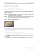
Cable Preparation
The cable run is determined during the site survey. Note that the length of the cables may need to
be slightly different, depending on the position of the buss bar relative to the BTS.
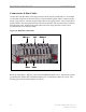
• Cut nine (9) pieces of cable for the main feeder cables to connect the nine RFS
connectors to the surge protectors on the system ground buss bar. Leave enough extra
length for the service loop below the RFS and for connection to the surge protectors.
• Cut eight (8) pieces of cable for the jumper cables to connect the surge protectors on the
system ground buss bar to the eight (8) RF input connectors on the back of the BTS.
Leave enough extra cable length for service.
• Cut one (1) piece of cable for the jumper cable to connect the surge protector on the
system ground buss bar to the CAL connector on the back of the BTS. Leave enough
extra cable length for service.
• Cut a piece of LMR 400 cable to connect each of the GPS antennas to the surge
protectors on the system ground buss bar. Leave enough extra cable length for service.
The maximum length of the LMR 400 cable for the GPS antenna is 100 feet.
• Cut a piece of LMR 400 cable to connect the surge protectors on the system ground buss
bar to each GPS connector on the back of the BTS. Leave enough extra cable length for
service. If there is more than one BTS co-located in the installation, two GPS antennas
can serve all BTS’s in the installation.
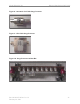
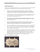
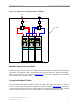
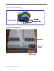
• The cable from the GPS antenna (after it goes through the surge protector) is connected
to the antenna input of the GPS distribution amplifier (Figure 12). The output ports of the
GPS distribution amplifier are connected to the GPS inputs of the BTS. The GPS
distribution amplifier is powered by the GPS antenna input. The drawing in Figure 13
depicts the placement of the shared GPS resources among three BTS’s.
Figure 12: GPS Distribution Amplifier