Catalyst 3560 Switch Getting Started Guide INCLUDING LICENSE AND WARRANTY 1 2 3 4 5 6 7 8 9 10 11 12 13 14 About this Guide Taking Out What You Need Running Express Setup Managing the Switch Installing the Switch Connecting to the Switch Ports In Case of Difficulty Obtaining Documentation Documentation Feedback Cisco Product Security Overview Product Alerts and Field Notices Obtaining Technical Assistance Obtaining Additional Publications and Information Cisco Limited Lifetime Hardware Warranty Terms
1 About this Guide This guide provides instructions on how to use Express Setup to configure your Catalyst switch. Also covered are switch management options, basic rack-mounting procedures, port and module connections, power connection procedures, and troubleshooting help. For additional installation and configuration information for Catalyst 3560 switches, see the Catalyst 3560 documentation on Cisco.com.
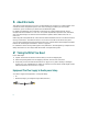
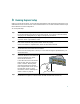
Shipping Box Contents (All Catalyst 3560 Switches Except the Catalyst 3560-8PC Switch) 1 SYST RPS 1X STAT DUPLX SPEED PoE MODE 2 3 4 5 6 7 8 9 10 11 12 13 14 15 16 17 15X 17X 18 19 20 21 22 23 2X 24 25 26 27 28 29 30 31 32 33 31X 33X 16X 34 35 36 37 38 39 40 18X 41 42 43 44 45 46 47 Catalyst 3560 G SERIES PoE- 48 48 47X 32X 34X 49 51 48X 50 52 Catalyst 3560 switch Two 19-inch mounting brackets Four number-12 Phillips machine screws Four number-8 P
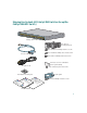
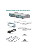
Shipping Box Contents (only the Catalyst 3560-8PC Switch) SYST STAT DPLX SPD PoE CONSOL E 1x 2x 3x 4x MODE 5x 6x 7x 8x Catalyst 35 60 SERIES Po E-8 1 Catalyst 3560 switch Mounting magnet Console cable Screw template AC power cord (AC-powered switches only) Three number-8 Phillips pan-head screws e nc ia on pl ati om m h r C o itc y Inf e Sw or y at et th 0 ul af for 56 eg S t3 R nd ys a al at C h itc w de S ui 0 G 56 ed t 3 art ys t al S at ng C tti e G p hi rs ne rd w ca n co O io is
3 Running Express Setup When you first set up the switch, you should use Express Setup to enter the initial IP information. This enables the switch to connect to local routers and the Internet. You can then access the switch through the IP address for further configuration. To run Express Setup: Step 1 Make sure that nothing is connected to the switch. During Express Setup, the switch acts as a DHCP server.
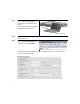
Step 7 Connect a Category 5 Ethernet cable to any 10/100 or 10/100/1000 Ethernet port on the switch front panel. 1 SYST RPS 1X STAT DUPLX SPEED PoE MODE 2 3 4 5 6 7 8 9 10 11 12 13 14 15 16 17 15X 17X 2X 18 19 20 21 22 23 24 25 26 27 28 29 30 31 32 33 31X 33X 16X 18X 34 35 36 37 38 39 40 41 42 43 44 45 46 47 Catalyst 3560G 48 SERIES PoE-48 47X 32X 34X 49 51 Connect the other end of the cable to the Ethernet port on your PC.
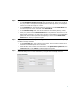
Step 10 Enter this information in the Network Settings fields: • In the Management Interface (VLAN ID) field, the default is 1. Enter a new VLAN ID only if you want to change the management interface through which you manage the switch. The VLAN ID range is 1 to 1001. • In the IP Address field, enter the IP address of the switch. In the IP Subnet Mask field, click the drop-down arrow, and select an IP Subnet Mask. • In the Default Gateway field, enter the IP address for the default gateway (router).
Step 13 (Optional) Enter this information in the Advanced Setting fields: • In the Telnet Access field, click Enable if you are going to use Telnet to manage the switch by using the command-line interface (CLI). If you enable Telnet access, you must enter a Telnet password. • In the Telnet Password field, enter a password. The Telnet password can be from 1 to 25 alphanumeric characters, is case sensitive, allows embedded spaces, but does not allow spaces at the beginning or end.
Refreshing the PC IP Address After you complete Express Setup, you should refresh the PC IP address. For a dynamically assigned IP address, disconnect the PC from the switch, and reconnect it to the network. The network DHCP server assigns a new IP address to the PC. For a statically assigned IP address, change it to the previously configured IP address.
3. Download the Network Assistant installer, and run it. (You can run it directly from the Web if your browser offers this choice.) 4. When you run the installer, follow the displayed instructions. In the final panel, click Finish to complete the Network Assistant installation. Refer to the Network Assistant online help and the getting started guide for more information. Command-Line Interface You can enter Cisco IOS commands and parameters through the CLI.
5 Installing the Switch Depending on the switch model, you can install the switch in a rack, on a wall, on or under a desk or shelf, and with a magnet or rack-mount brackets. This section covers rack-, desk-, shelf-, and magnet-mounting a switch. Depending on the switch, For alternate mounting procedures, see the Catalyst 3560 Switch Hardware Installation Guide on Cisco.com.
• When placing the Catalyst 3560-8PC switch on a flat horizontal surface without the magnet, we strongly recommend that you attach the rubber feet to the switch. Doing so helps prevent airflow restriction and overheating. • Do not stack switches or place Catalyst 3560-8PC switches side-by-side, unless they are separated all around by at least 3 inches (7.6 cm) of clearance from each other. • Do not wall-mount the Catalyst 3560-8PC switch with its front panel facing up or to the side.
Warning Installation of the equipment must comply with local and national electrical codes. Statement 1074 Warning To prevent bodily injury when mounting or servicing this unit in a rack, you must take special precautions to ensure that the system remains stable. The following guidelines are provided to ensure your safety: • This unit should be mounted at the bottom of the rack if it is the only unit in the rack.
Warning For connections outside the building where the equipment is installed, the following ports must be connected through an approved network termination unit with integral circuit protection: 10/100/1000 Ethernet. Statement 1044 Warning Voltages that present a shock hazard may exist on Power over Ethernet (PoE) circuits if interconnections are made using uninsulated exposed metal contacts, conductors, or terminals.
Attaching the Brackets Use four Phillips flat-head screws to attach the long side of the brackets to Catalyst 3560 switches in one of three mounting positions.
Mounting the Switch in a Rack Use the black Phillips machine screw to attach the cable guide to the left or right bracket. Use the four number-12 Phillips machine screws to attach the brackets to the rack.
Securing the Switch on a Desk or Shelf (only the Catalyst 3560-8PC Switch) Note This section is specific to the Catalyst 3560-8PC switch. For installation information for other Catalyst 3560 switches, see “Rack-Mounting the Switch (All Catalyst 3560 Switches Except the Catalyst 3560-8PC Switch)” section on page 14. To place the switch on a desk without using the mounting screws, simply attach the four rubber feet on the bottom panel of the switch.
4. Place the switch onto the mounting screws, and slide it forward until it locks in place.
Mounting the Switch with a Magnet Panel (only the Catalyst 3560-8PC Switch) Note This section only applies to the Catalyst 3560-8PC switch. For installation information for all other Catalyst 3560 switches, see “Rack-Mounting the Switch (All Catalyst 3560 Switches Except the Catalyst 3560-8PC Switch)” section on page 14. Follow these steps: 1. Position the mounting magnet on the mounting surface. 2. Place the bottom of the switch on the mounting magnet.
6 Connecting to the Switch Ports This section describes how to connect to the switch ports, the SFP module ports, and to the dual-purpose ports. It also describes how to verify your connections. For additional cabling information, see the Catalyst 3560 Switch Hardware Installation Guide on Cisco.com.
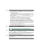
Installing an SFP Module and Connecting to a Module Port Follow these steps: Step 1 Grasp the module on the sides, and insert it into the switch slot until you feel the connector snap into place. 33 34 35 33X 36 37 38 39 40 41 42 43 44 45 46 47 Catalyst 35 60G SERIES 48 PoE-48 47X 34X 1 49 51 2 1 50 48X 52 2 SFP module Step 2 Insert an appropriate cable into the module port.
Connecting to a Dual-Purpose Port For information about using the SFP module port, see the “Installing an SFP Module and Connecting to a Module Port” section on page 21. Follow these steps: Insert either an RJ-45 connector to the 10/100/1000 port, or install an SFP module into the SFP module slot, and connect a cable to the SFP module port. Only one port can be active at a time. If both ports are connected, the SFP module port has priority. The priority setting is not configurable.
7 In Case of Difficulty If you experience difficulty, help is available here and on Cisco.com. This section includes Express Setup troubleshooting, how to reset the switch, how to access help online, and where to find more information.
• Did you wait 30 seconds after connecting the If not, wait 30 seconds, re-enter 10.0.0.1 in the switch and the PC before entering the IP browser, and press Enter. address in your browser? • Did you enter the wrong address in the browser, or is there an error message? If yes, re-enter 10.0.0.1 in the browser, and press Enter. Resetting the Switch This section describes how to reset the switch by rerunning Express Setup.
• Troubleshooting tools • Field notices and security advisories Follow these steps: 1. Open your browser, and go to http://www.cisco.com/. 2. Click Technical Support. 3. Click Product Support > Switches > LAN and ATM Switches > Catalyst 3560 Series Switches > Troubleshooting. 4. Click the subject that addresses the problem that you are experiencing. For More Information For more information about the switch, see these documents on Cisco.
8 Obtaining Documentation Cisco documentation and additional literature are available on Cisco.com. This section explains the product documentation resources that Cisco offers. Cisco.com You can access the most current Cisco documentation at this URL: http://www.cisco.com/techsupport You can access the Cisco website at this URL: http://www.cisco.com You can access international Cisco websites at this URL: http://www.cisco.com/public/countries_languages.
9 Documentation Feedback You can provide feedback about Cisco technical documentation on the Cisco Technical Support & Documentation site area by entering your comments in the feedback form available in every online document. 10 Cisco Product Security Overview Cisco provides a free online Security Vulnerability Policy portal at this URL: http://www.cisco.com/en/US/products/products_security_vulnerability_policy.
In an emergency, you can also reach PSIRT by telephone: • 1 877 228-7302 • 1 408 525-6532 Tip We encourage you to use Pretty Good Privacy (PGP) or a compatible product (for example, GnuPG) to encrypt any sensitive information that you send to Cisco. PSIRT can work with information that has been encrypted with PGP versions 2.x through 9.x. Never use a revoked encryption key or an expired encryption key.
Cisco Technical Support & Documentation Website The Cisco Technical Support & Documentation website provides online documents and tools for troubleshooting and resolving technical issues with Cisco products and technologies. The website is available 24 hours a day at this URL: http://www.cisco.com/techsupport Access to all tools on the Cisco Technical Support & Documentation website requires a Cisco.com user ID and password.
Submitting a Service Request Using the online TAC Service Request Tool is the fastest way to open S3 and S4 service requests. (S3 and S4 service requests are those in which your network is minimally impaired or for which you require product information.) After you describe your situation, the TAC Service Request Tool provides recommended solutions. If your issue is not resolved using the recommended resources, your service request is assigned to a Cisco engineer.
13 Obtaining Additional Publications and Information Information about Cisco products, technologies, and network solutions is available from various online and printed sources. • The Cisco Online Subscription Center is the website where you can sign up for a variety of Cisco e-mail newsletters and other communications. Create a profile and then select the subscriptions that you would like to receive. To visit the Cisco Online Subscription Center, go to this URL: http://www.cisco.
• “What’s New in Cisco Documentation” is an online publication that provides information about the latest documentation releases for Cisco products. Updated monthly, this online publication is organized by product category to direct you quickly to the documentation for your products. You can view the latest release of “What’s New in Cisco Documentation” at this URL: http://www.cisco.com/univercd/cc/td/doc/abtunicd/136957.htm • World-class networking training is available from Cisco.
c. Click Go. The Cisco warranty page appears. d. Read the document online, or click the PDF icon to download and print the document in Adobe Portable Document Format (PDF). You can also contact the Cisco service and support website for assistance: http://www.cisco.com/public/Support_root.shtml.
Corporate Headquarters Cisco Systems, Inc. 170 West Tasman Drive San Jose, CA 95134-1706 USA www.cisco.com Tel: 408 526-4000 800 553-NETS (6387) Fax: 408 526-4100 European Headquarters Cisco Systems International BV Haarlerbergpark Haarlerbergweg 13-19 1101 CH Amsterdam The Netherlands www-europe.cisco.com Tel: 31 0 20 357 1000 Fax: 31 0 20 357 1100 Americas Headquarters Cisco Systems, Inc. 170 West Tasman Drive San Jose, CA 95134-1706 USA www.cisco.