Catalyst 6500 Series Switch Content Switching Module with SSL Installation Note Product Number: WS-X6066-SLB-S-K9 This publication describes how to install the Content Switching Module with SSL (CSM-S) in the Catalyst 6500 series switches and includes the software and hardware requirements. Note The term SSL daughter card refers to a Secure Socket Layer (SSL) termination daughter card that accelerates SSL transactions.
Safety Overview • Obtaining Technical Assistance, page 26 • Obtaining Additional Publications and Information, page 27 Safety Overview Warning IMPORTANT SAFETY INSTRUCTIONS This warning symbol means danger. You are in a situation that could cause bodily injury. Before you work on any equipment, be aware of the hazards involved with electrical circuitry and be familiar with standard practices for preventing accidents.
Safety Overview Warnung WICHTIGE SICHERHEITSHINWEISE Dieses Warnsymbol bedeutet Gefahr. Sie befinden sich in einer Situation, die zu Verletzungen führen kann. Machen Sie sich vor der Arbeit mit Geräten mit den Gefahren elektrischer Schaltungen und den üblichen Verfahren zur Vorbeugung vor Unfällen vertraut. Suchen Sie mit der am Ende jeder Warnung angegebenen Anweisungsnummer nach der jeweiligen Übersetzung in den übersetzten Sicherheitshinweisen, die zusammen mit diesem Gerät ausgeliefert wurden.
Safety Overview Varning! VIKTIGA SÄKERHETSANVISNINGAR Denna varningssignal signalerar fara. Du befinner dig i en situation som kan leda till personskada. Innan du utför arbete på någon utrustning måste du vara medveten om farorna med elkretsar och känna till vanliga förfaranden för att förebygga olyckor. Använd det nummer som finns i slutet av varje varning för att hitta dess översättning i de översatta säkerhetsvarningar som medföljer denna anordning.
Safety Overview Aviso INSTRUÇÕES IMPORTANTES DE SEGURANÇA Este símbolo de aviso significa perigo. Você se encontra em uma situação em que há risco de lesões corporais. Antes de trabalhar com qualquer equipamento, esteja ciente dos riscos que envolvem os circuitos elétricos e familiarize-se com as práticas padrão de prevenção de acidentes. Use o número da declaração fornecido ao final de cada aviso para localizar sua tradução nos avisos de segurança traduzidos que acompanham o dispositivo.
Safety Overview Catalyst 6500 Series Switch Content Switching Module with SSL Installation Note 6 78-16856-01
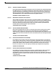
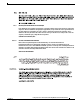
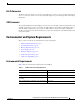
Front Panel Description Front Panel Description These sections describe the physical attributes of the CSM-S: • LEDs, page 8 • RJ-45 Connector, page 9 • SSL Connector, page 9 Figure 1 shows the CSM-S front panel. Status LED Content Switching Module with SSL Front Panel SSL Certificate Management Connector RJ-45 Crypto Note 113438 Figure 1 The RJ-45 connector is covered by a removable plate.
Front Panel Description You are required to make initial SSL daughter card configurations through a direct connection to the CSM-S Certificate Management port (Cert. Mgt). After the initial configurations, you can make an SSH or Telnet connection to further configure the module. See Chapter 5 in the Catalyst 6500 Series Content Switching Module with SSL Installation and Configuration Note.
Environmental and System Requirements RJ-45 Connector The RJ-45 connector, which is covered by a removable plate, is used to connect a management station device or a test device. This connector is used by field engineers to perform testing and to obtain dump information. SSL Connector The Certificate Management (Cert. Mgt.) port connector is used for SSL certificate management and is available to make the necessary connection to the SSL daughter card for initial configuration purposes.
Environmental and System Requirements System Requirements Before you install the CSM-S in the Catalyst 6500 series switch, make sure that the switch meets the hardware and software requirements listed in this section. Caution You can use the Multilayer Switch Feature Card (MSFC2), which is internal to the Catalyst 6500 series switch, to route traffic on either the client side or the server side of the CSM-S, but not both simultaneously (unless policy-based routing is used).
Installing the CSM-S Software Requirements Caution The CSM-S release is not supported by the Catalyst operating system. Table 4 lists the software versions for the CSM-S. Table 4 CSM-S Software Requirements CSM-S Software Release Software Part Number Hardware Catalyst Operating System Cisco IOS Release 2,1(1) SC6K-1.1-CSM-S WS-X6066-SLB-S-K9 Not Applicable Cisco IOS software Release 12.
Installing the CSM-S Preparing to Install the CSM-S Before installing the CSM-S, make sure that the following items are available: • Catalyst 6500 series switch chassis • Management station that is available through a Telnet or a console connection to perform configuration tasks Required Tools These tools are required to install the CSM-S in the Catalyst 6500 series switches: • Flat-blade screwdriver • Phillips-head screwdriver • Wrist strap or other grounding device • Antistatic mat or antistat
Installing the CSM-S • Slot 1 is reserved for the supervisor engine. • Slot 2 can be used for a redundant supervisor engine if the supervisor engine in slot 1 fails. • If a redundant supervisor engine is not required, slots 2 through 6 on the 6-slot chassis, slots 2 through 9 on the 9-slot chassis, and slots 2 through 13 on the 13-slot chassis are available for switching modules, such as the CSM-S.
Installing the CSM-S Step 6 If the slot from which you removed the module is to remain empty, install a module filler plate to keep dust out of the chassis and to maintain proper airflow through the chassis. Warning Blank faceplates (filler panels) serve three important functions: they prevent exposure to hazardous voltages and currents inside the chassis; they contain electromagnetic interference (EMI) that might disrupt other equipment; and they direct the flow of cooling air through the chassis.
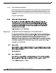
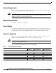
Installing the CSM-S Figure 2 Positioning the Module in a Horizontal Slot Chassis Insert module between slot guides EMI gasket 3 4 5 6 4 5 6 WS-X6K-SUP2-2GE 1 ST AT US SY ST OL EM T E NS CO R M PW GM SE Switch 100% T Load CONSOLE PORT MODE RE PORT 1 PORT 2 CONSOLE SUPERVISOR2 PCMCIA EJECT 1% WS-X6K-SUP2-2GE 2 ST AT US SY ST OL EM CO T E NS R PW M GM SE Switch 100% T Load CONSOLE PORT MODE RE PORT 1 PORT 2 CONSOLE SUPERVISOR2 PCMCIA EJECT 1% 3 4 F
Installing the CSM-S Figure 3 Clearing the EMI Gasket in a Horizontal Slot Chassis WS-X6K-SUP2-2GE T M LE G O US EM M T AT NS R ST SE ST SY CO PW RE 1 Switch 100% CONSOLE Load CONSOLE PORT MODE SUPERVISOR2 PORT 1 PCMCIA PORT 2 EJECT 1% WS-X6K-SUP2-2GE NK LI T M LE G O US EM M T AT NS R ST SE ST SY CO PW RE 2 Switch 100% CONSOLE SUPERVISOR2 CONSOLE PORT MODE PORT 1 PCMCIA NK LI Load PORT 2 EJECT 1% NK LI NK LI 3 Press down 4 FAN STATUS 5 Press down WS-X6224 S TU STA VE TI AC
Installing the CSM-S Figure 4 Ejector Lever Closure in a Horizontal Slot Chassis WS-X6K-SUP2-2GE T M LE G O US EM M T AT NS R ST SE ST SY CO PW RE 1 Switch 100% CONSOLE SUPERVISOR2 Load CONSOLE PORT MODE PORT 1 PCMCIA PORT 2 EJECT 1% WS-X6K-SUP2-2GE NK LI T M LE G O US EM M T AT NS R ST SE ST SY CO PW RE 2 Switch 100% CONSOLE SUPERVISOR2 PORT 1 PCMCIA NK LI Load CONSOLE PORT MODE PORT 2 EJECT 1% NK LI NK LI 3 4 FAN STATUS 5 WS-C6500-SFM S TU STA SWITCH FABRIC MDL VE TI AC
Installing the CSM-S Figure 5 Positioning the Module in a Vertical Slot Chassis Ejector lever fully extended WS-C6500-SFM SWITCH FABRIC MDL FAN STATUS WS-X6K-SUP2-2GE TUS SYS MT OLE MG TEM NS R SET RE PW CO MT E M S OL T MG TU R NS SE STE RE PW CO SY STA STA WS-X6K-SUP2-2GE SUPERVISOR2 SUPERVISOR2 ST AT CONSOLE CONSOLE AC US PORT MODE PORT MODE CONSOLE WS-X6224 24 PORT 100FX CONSOLE TIV E ST AT US AC TIV E PCMCIA PCMCIA EJECT EJECT Switch Switch 1% 100% 1% 100% Load L
Installing the CSM-S Figure 6 Clearing the EMI Gasket in a Vertical Slot Chassis Gap between the module EMI gasket and the module above it 1 mm WS-C6500-SFM SWITCH FABIRD MDL US AT ST E TIV AC FAN STATUS WS-X6K-SUP2-2GE STA TUS SYS AT US MT OLE MG TEM NS R SET RE PW CO ST MT E M S OL T MG TU R NS SE STE RE PW CO SY STA WS-X6K-SUP2-2GE SUPERVISOR2 SUPERVISOR2 WS-X6224 24 PORT 100FX AC E CONSOLE CONSOLE TIV PORT CONSOLE PORT MODE MODE CONSOLE Press left PCMCIA PCMCIA EJECT EJECT
Verifying the Installation Figure 7 Ejector Lever Closure in a Vertical Slot Chassis FAN STATUS ST WS-X6K-SUP2-2GE SUPERVISOR2 AT US SY ST CO EM NS O PW LE R M M RE G SE T S TU STA T M LE G O T M EM US R NS SE ST AT RE PW CO SY ST WS-X6K-SUP2-2GE SUPERVISOR2 WS-X6224 24 PORT 100FX T CONSOLE CONSOLE VE TI AC CONSOLE PORT MODE CONSOLE PORT MODE PCMCIA PCMCIA EJECT EJECT 1% Switch Switch 100% 1% 100% SE LE PORT 1 PORT 1 XT Load Load NE CT 63587 PORT 2 PORT 2 All
Related Documentation To understand the Cisco IOS command-line interface and Cisco IOS command modes, refer to Chapter 2, “Command-Line Interfaces,” in the Catalyst 6500 Series Switch Cisco IOS Software Configuration Guide. To understand the Catalyst operating system command-line interface and Catalyst operating system command modes, refer to Chapter 2, “Command-Line Interfaces,” in the Catalyst 6500 Series Switch Configuration Guide.
Translated Safety Warnings Warnung Avvertenza Advarsel Aviso ¡Advertencia! Unsichtbare Laserstrahlung. Radiazione laser invisibile. Usynlig laserstråling. Radiação laser invisível presente. Existe radiación láser invisible. Varning! Nu pågående osynlig laserstrålning.
Translated Safety Warnings Warnung Blanke Faceplates und Abdeckungen haben drei wichtigen Funktionen: (1) Sie schützen vor gefährlichen Spannungen und Strom innerhalb des Chassis; (2) sie halten elektromagnetische Interferenzen (EMI) zurück, die andere Geräte stören könnten; (3) sie lenken den kühlenden Luftstrom durch das Chassis. Das System darf nur betrieben werden, wenn alle Karten, Faceplates, Voder- und Rückabdeckungen an Ort und Stelle sind.
Obtaining Documentation Obtaining Documentation Cisco documentation and additional literature are available on Cisco.com. Cisco also provides several ways to obtain technical assistance and other technical resources. These sections explain how to obtain technical information from Cisco Systems. Cisco.com You can access the most current Cisco documentation at this URL: http://www.cisco.com/univercd/home/home.htm You can access the Cisco website at this URL: http://www.cisco.
Documentation Feedback You can order Cisco documentation in these ways: • Registered Cisco.com users (Cisco direct customers) can order Cisco product documentation from the Ordering tool: http://www.cisco.com/en/US/partner/ordering/ • Nonregistered Cisco.com users can order documentation through a local account representative by calling Cisco Systems Corporate Headquarters (California, USA) at 408 526-7208 or, elsewhere in North America, by calling 1 800 553-NETS (6387).
Obtaining Technical Assistance Tip We encourage you to use Pretty Good Privacy (PGP) or a compatible product to encrypt any sensitive information that you send to Cisco. PSIRT can work from encrypted information that is compatible with PGP versions 2.x through 8.x. Never use a revoked or an expired encryption key. The correct public key to use in your correspondence with PSIRT is the one that has the most recent creation date in this public key server list: http://pgp.mit.
Obtaining Additional Publications and Information Submitting a Service Request Using the online TAC Service Request Tool is the fastest way to open S3 and S4 service requests. (S3 and S4 service requests are those in which your network is minimally impaired or for which you require product information.) After you describe your situation, the TAC Service Request Tool provides recommended solutions.
Obtaining Additional Publications and Information • Cisco Press publishes a wide range of general networking, training and certification titles. Both new and experienced users will benefit from these publications. For current Cisco Press titles and other information, go to Cisco Press at this URL: http://www.ciscopress.com • Packet magazine is the Cisco Systems technical user magazine for maximizing Internet and networking investments.