Cisco Aironet 1100 Series Access Point Hardware Installation Guide December 2006 Corporate Headquarters Cisco Systems, Inc. 170 West Tasman Drive San Jose, CA 95134-1706 USA http://www.cisco.
THE SPECIFICATIONS AND INFORMATION REGARDING THE PRODUCTS IN THIS MANUAL ARE SUBJECT TO CHANGE WITHOUT NOTICE. ALL STATEMENTS, INFORMATION, AND RECOMMENDATIONS IN THIS MANUAL ARE BELIEVED TO BE ACCURATE BUT ARE PRESENTED WITHOUT WARRANTY OF ANY KIND, EXPRESS OR IMPLIED. USERS MUST TAKE FULL RESPONSIBILITY FOR THEIR APPLICATION OF ANY PRODUCTS.
C ON T E N T S Preface vii Audience Purpose vii vii Organization vii Conventions viii Related Publications x Obtaining Documentation x Cisco.
Contents Repeater Unit that Extends Wireless Range 1-7 Central Unit in an All-Wireless Network 1-8 Workgroup Bridge Configuration 1-8 Network Example with Lightweight Access Points CHAPTER 2 Installing the Access Point 2-1 Safety Information 2-2 FCC Safety Compliance Statement General Safety Guidelines 2-2 Warnings 1-9 2-2 2-2 Unpacking the Access Point 2-3 Package Contents 2-3 Basic Installation Guidelines 2-3 Access Point Layout and Connectors LEDs 2-4 2-4 Controller Discovery Process for Ligh
Contents Installing a 2.
Contents APPENDIX A Translated Safety Warnings APPENDIX B Declarations of Conformity and Regulatory Information A-1 B-1 Manufacturers Federal Communication Commission Declaration of Conformity Statement VCCI Statement for Japan B-2 B-3 Department of Communications—Canada B-3 Canadian Compliance Statement B-3 European Community, Switzerland, Norway, Iceland, and Liechtenstein B-4 Declaration of Conformity with Regard to the R&TTE Directive 1999/5/EC Declaration of Conformity for RF Exposure B-6
Preface Audience This guide is for the networking professional who installs and manages the Cisco Aironet 1100 Series Access Point. The 1100 series access point is available in autonomous and lightweight configurations. To use this guide with autonomous access points, you should have experience working with Cisco IOS software and be familiar with the concepts and terminology of wireless local area networks.
Preface Conventions Chapter 3, “Mounting Instructions,” describes how to mount the access point on a desktop, wall, or ceiling. Chapter 4, “2.4-GHz Radio Upgrade for Autonomous Access Points,” provides upgrade instructions for changing the 2.4 GHz radio Chapter 5, “Troubleshooting Autonomous Access Points,” provides troubleshooting procedures for basic problems with the autonomous access point.
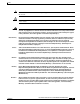
Preface Conventions Note Means reader take note. Notes contain helpful suggestions or references to materials not contained in this manual. Caution Means reader be careful. In this situation, you might do something that could result equipment damage or loss of data. Warning This warning symbol means danger. You are in a situation that could cause bodily injury.
Preface Related Publications Advarsel Aviso Dette varselsymbolet betyr fare. Du befinner deg i en situasjon som kan føre til personskade. Før du utfører arbeid på utstyr, må du være oppmerksom på de faremomentene som elektriske kretser innebærer, samt gjøre deg kjent med vanlig praksis når det gjelder å unngå ulykker. (Hvis du vil se oversettelser av de advarslene som finnes i denne publikasjonen, kan du se i vedlegget "Translated Safety Warnings" [Oversatte sikkerhetsadvarsler].
Preface Documentation Feedback Cisco.com You can access the most current Cisco documentation at this URL: http://www.cisco.com/techsupport You can access the Cisco website at this URL: http://www.cisco.com You can access international Cisco websites at this URL: http://www.cisco.com/public/countries_languages.shtml Product Documentation DVD The Product Documentation DVD is a library of technical product documentation on a portable medium.
Preface Product Alerts and Field Notices • Obtain assistance with security incidents that involve Cisco products • Register to receive security information from Cisco A current list of security advisories, security notices, and security responses for Cisco products is available at this URL: http://www.cisco.
Preface Obtaining Technical Assistance To access the Product Alert Tool, you must be a registered Cisco.com user. Registered users can access the tool at this URL: http://tools.cisco.com/Support/PAT/do/ViewMyProfiles.do?local=en To register as a Cisco.com user, go to this URL: http://tools.cisco.com/RPF/register/register.do Obtaining Technical Assistance Cisco Technical Support provides 24-hour-a-day award-winning technical assistance. The Cisco Support website on Cisco.
Preface Obtaining Technical Assistance Tip Displaying and Searching on Cisco.com If you suspect that the browser is not refreshing a web page, force the browser to update the web page by holding down the Ctrl key while pressing F5. To find technical information, narrow your search to look in technical documentation, not the entire Cisco.com website. After using the Search box on the Cisco.
Preface Obtaining Additional Publications and Information Submitting a Service Request Using the online TAC Service Request Tool is the fastest way to open S3 and S4 service requests. (S3 and S4 service requests are those in which your network is minimally impaired or for which you require product information.) After you describe your situation, the TAC Service Request Tool provides recommended solutions.
Preface Obtaining Additional Publications and Information • The Cisco Product Quick Reference Guide is a handy, compact reference tool that includes brief product overviews, key features, sample part numbers, and abbreviated technical specifications for many Cisco products that are sold through channel partners. It is updated twice a year and includes the latest Cisco channel product offerings. To order and find out more about the Cisco Product Quick Reference Guide, go to this URL: http://www.cisco.
C H A P T E R 1 Overview The Cisco Aironet Cisco Aironet 1100 Series Access Point series access point is available in autonomous and lightweight configurations. The autonomous access points can support standalone network configurations with all configuration settings maintained within the access points. The lightweight access points operate in conjunction with a Cisco wireless LAN controller with all configuration information maintained within the controller.
Chapter 1 Overview The lightweight access point contains one integrated radio: a 2.4-GHz radio (IEEE 802.11g). Using a controller, you can configure the radio settings. In the Cisco Centralized Wireless LAN architecture, access points operate in the lightweight mode (as opposed to autonomous mode). The lightweight access points associate to a controller. The controller manages the configuration, firmware, and controls transactions such as 802.1x authentication.
Chapter 1 Overview Hardware Features Hardware Features This section describes the access point features. Refer to Appendix C, “Access Point Specifications,” for a list of access point specifications.
Chapter 1 Overview Hardware Features LEDs The three LEDs on the top of the access point report Ethernet activity, association status, and radio activity. • The Ethernet LED signals Ethernet traffic on the wired LAN, or Ethernet infrastructure. This LED is normally green when an Ethernet cable is connected, and blinks green when a packet is received or transmitted over the Ethernet infrastructure. The LED is off when the Ethernet cable is not connected. • The status LED signals operational status.
Chapter 1 Overview Network Examples with Autonomous Access Points UL 2043 Certification The access point is encased in a durable plastic enclosure having adequate fire resistance and low smoke-producing characteristics suitable for operation in a building's environmental air space, such as above suspended ceilings, in accordance with Section 300-22(c) of the NEC, and with Sections 2-128, 12-010(3) and 12-100 of the Canadian Electrical Code, Part 1, C22.1.
Chapter 1 Overview Network Examples with Autonomous Access Points Root Unit on a Wired LAN An autonomous access point connected directly to a wired LAN provides a connection point for wireless users. If more than one autonomous access point is connected to the LAN, users can roam from one area of a facility to another without losing their connection to the network. As users move out of range of one access point, they automatically connect to the network (associate) through another access point.
Chapter 1 Overview Network Examples with Autonomous Access Points Repeater Unit that Extends Wireless Range An autonomous access point can be configured as a stand-alone repeater to extend the range of your infrastructure or to overcome an obstacle that blocks radio communication. The repeater forwards traffic between wireless users and the wired LAN by sending packets to either another repeater or to an access point connected to the wired LAN.
Chapter 1 Overview Network Examples with Autonomous Access Points Central Unit in an All-Wireless Network In an all-wireless network, an autonomous access point acts as a stand-alone root unit. The autonomous access point is not attached to a wired LAN; it functions as a hub linking all stations together. The access point serves as the focal point for communications, increasing the communication range of wireless users. Figure 1-5 shows an autonomous access point in an all-wireless network.
Chapter 1 Overview Network Example with Lightweight Access Points In Figure 1-7, the autonomous unit is configured in workgroup bridge mode and is associated to a Cisco Aironet root bridge as a wireless bridge device. This configuration allows the Ethernet-enabled devices pass Ethernet traffic to and from the main LAN using the workgroup bridge. The main advantage of this configuration is that the wireless communication link can be over a longer distance than an access point supports.
Chapter 1 Overview Network Example with Lightweight Access Points Cisco Aironet 1100 Series Access Point Hardware Installation Guide 1-10 OL-4309-07
C H A P T E R 2 Installing the Access Point This chapter describes the setup of the access point and includes the following sections: • Safety Information, page 2-2 • Warnings, page 2-2 • Unpacking the Access Point, page 2-3 • Basic Installation Guidelines, page 2-3 • Controller Discovery Process for Lightweight Access Points, page 2-5 • Deploying the Access Points on the Wireless Network, page 2-5 • Connecting the Ethernet and Power Cables, page 2-7 Cisco Aironet 1100 Series Access Point Ha
Chapter 2 Installing the Access Point Safety Information Safety Information Follow the guidelines in this section to ensure proper operation and safe use of the access point. FCC Safety Compliance Statement The FCC with its action in ET Docket 96-8 has adopted a safety standard for human exposure to radio frequency (RF) electromagnetic energy emitted by FCC certified equipment.
Chapter 2 Installing the Access Point Unpacking the Access Point Unpacking the Access Point Follow these steps to unpack the access point: Step 1 Open the shipping container and carefully remove the contents. Step 2 Return all packing materials to the shipping container and save it. Step 3 Ensure that all items listed in the “Package Contents” section are included in the shipment. Check each item for damage. If any item is damaged or missing, notify your authorized Cisco sales representative.
Chapter 2 Installing the Access Point Basic Installation Guidelines Access Point Layout and Connectors Figure 2-1 shows the access point layout and connectors. Figure 2-1 2 3 4 6 5 81180 1 Access Point Layout and Connectors 1 48-VDC power port 4 Mode button 2 Ethernet port (RJ-45) 5 Status LEDs 3 Cable lock slot 6 Antenna LEDs The three LEDs on the top of the access point report Ethernet activity, association status, and radio activity.
Chapter 2 Installing the Access Point Controller Discovery Process for Lightweight Access Points Controller Discovery Process for Lightweight Access Points The lightweight access point supports these controller discovery processes: • DHCP server discovery—Uses DHCP Option 43 to provide controller IP addresses to the access points. Cisco switches support a DHCP server option. For additional information, refer to the “Configuring DHCP Option 43 for Lightweight Access Points” section on page F-1.
Chapter 2 Installing the Access Point Deploying the Access Points on the Wireless Network b. Mount the access point at the indicated destination using the specified mounting method. For specific instructions, see these sections: – Horizontal or vertical surface, such as a ceiling or wall (refer to the Mounting on a Horizontal or Vertical Surface, page 3-3). – Below a suspended ceiling (refer to the “Mounting on a Suspended Ceiling” section on page 3-4).
Chapter 2 Installing the Access Point Connecting the Ethernet and Power Cables Connecting the Ethernet and Power Cables The access point receives power through the Ethernet cable or an external power module. Figure 2-3 shows the power options for the access point.
Chapter 2 Installing the Access Point Connecting the Ethernet and Power Cables Connecting to an Ethernet Network with an Inline Power Source Follow these steps to connect the access point to the Ethernet LAN when you have an inline power source: Step 1 Connect the Ethernet cable to the RJ-45 Ethernet connector labeled Ethernet on the access point.
Chapter 2 Installing the Access Point Connecting the Ethernet and Power Cables Powering Up the Access Point When power is applied to the access point, it begins a routine power-up sequence that you can monitor by observing the three LEDs on top of the access point. After you observe all three LEDs turning green to indicate the starting of the Cisco IOS operating system, the Status LED blinks green signifying that Cisco IOS is operational.
Chapter 2 Installing the Access Point Connecting the Ethernet and Power Cables Cisco Aironet 1100 Series Access Point Hardware Installation Guide 2-10 OL-4309-07
C H A P T E R 3 Mounting Instructions This appendix contains mounting instructions for the access point and contains the following topics: • Overview, page 3-2 • Mounting on a Horizontal or Vertical Surface, page 3-3 • Mounting on a Suspended Ceiling, page 3-4 • Using the Security Hasp Adapter, page 3-7 • Mounting on a Cubical Wall Partition, page 3-8 • Using the Desktop Holster, page 3-9 • Using the Cable Lock Feature, page 3-11 Cisco Aironet 1100 Series Access Point Hardware Installation G
Chapter 3 Mounting Instructions Overview Overview The mounting brackets and hardware shipped with your access point enables you to mount it on any of the following surfaces: • Horizontal or vertical flat surfaces, such as walls or ceilings • Suspended ceilings • Cubical partition walls • Desktop or other suitable horizontal surface The 1100 series access point provides adequate fire resistance and low smoke-producing characteristics suitable for operation in a building's environmental air space,
Chapter 3 Mounting Instructions Mounting on a Horizontal or Vertical Surface The wall or ceiling mounting bracket also serves as a template for transferring the location of the bracket’s mounting holes to the mounting surface. Refer to Figure 3-1 to locate the various mounting holes for the method you intend to use.
Chapter 3 Mounting Instructions Mounting on a Suspended Ceiling Mounting on a Suspended Ceiling Follow these steps to mount your access point on a suspended ceiling. It may be helpful to refer to Figure 3-2 before beginning the process. Figure 3-2 Suspended Ceiling Mounting Bracket Parts 1 2 2 3 3 4 5 81190 5 1 Suspended ceiling T-rail 4 Wall or ceiling mounting bracket 2 Caddy fastener 5 Keps nut 3 Plastic spacer Step 1 Determine the location at which to mount the access point.
Chapter 3 Mounting Instructions Mounting on a Suspended Ceiling Step 8 Line up the mounting slots on the access point with the mounting rail on the wall or ceiling mounting bracket and slide it down the mounting rails until it clicks into place. See Figure 3-3.
Chapter 3 Mounting Instructions Mounting Above a Suspended Ceiling Mounting Above a Suspended Ceiling The access point mounting bracket is designed to be integrated into the T-bar grid above the tiles of a suspended ceiling. The access point uses a T-bar box hanger (not supplied) such as the Erico Caddy 512 or B-Line BA12 and should be oriented just above the top surface of a standard 5/8-in. (1.59 cm) ceiling tile. You may need to modify a thicker tile to allow room for the access point.
Chapter 3 Mounting Instructions Using the Security Hasp Adapter Step 4 Configure the ends of the T-bar box hanger to allow for maximum clearance above the ceiling tile. See the illustration above. Step 5 Attach the T-rail clips on the each end of the T-bar box hanger to the ceiling grid T-rails. Make sure the clips are securely attached to the T-rails. Step 6 Connect a drop wire to a building structural element and the hole provided in the bracket mounting clip.
Chapter 3 Mounting Instructions Mounting on a Cubical Wall Partition Step 3 Rotate the adapter to engage it with the security hasp. The hole in the adapter should be aligned with the hole in the security hasp. Step 4 Secure the adapter to the security hasp with a padlock. Your installation will look similar to Figure 3-7. Security Hasp with Padlock 81176 Figure 3-7 Mounting on a Cubical Wall Partition Follow these steps to mount the access point on a cubical wall partition.
Chapter 3 Mounting Instructions Using the Desktop Holster Step 6 Position the mounting bracket over the partition wall and adjust it to fit. See Figure 3-8. Cubicle Wall Bracket 81223 Figure 3-8 Using the Desktop Holster Follow these steps to mount the access point on a desktop or other horizontal surface using the supplied desktop holster. Step 1 Select a suitable location to place the holster. Step 2 Connect the Ethernet and power cables.
Chapter 3 Mounting Instructions Using the Desktop Holster Step 4 Insert the access point into the holster while guiding the cables so that they do not interfere with the sides of the holster. You will hear a click when the access point locks into place. See Figure 3-9.
Chapter 3 Mounting Instructions Using the Cable Lock Feature Using the Cable Lock Feature When you mount the access point using the cubical partition mount or desktop holster, you can secure the access point with your own security cable. Follow these steps to install the security cable. Note Cisco recommends using a Kensington Notebook Microstar (model number 64068) to secure your access point. Step 1 Loop the security cable around a nearby immovable object. Step 2 Insert the key into the lock.
Chapter 3 Mounting Instructions Using the Cable Lock Feature Cisco Aironet 1100 Series Access Point Hardware Installation Guide 3-12 OL-4309-07
C H A P T E R 4 2.4-GHz Radio Upgrade for Autonomous Access Points This chapter provides upgrade instructions for the autonomous access point 2.4-GHz (IEEE 802.11b-compliant or IEEE 802.11g-compliant) radio card and includes the following sections: • Upgrade Overview, page 4-2 • Unpacking the Radio, page 4-2 • Removing the Back Cover, page 4-3 • Removing a 2.4-GHz Radio, page 4-4 • Installing a 2.
Chapter 4 2.4-GHz Radio Upgrade for Autonomous Access Points Upgrade Overview Upgrade Overview This section provides instructions for upgrading the autonomous access point 2.4-GHz radio. Caution Your autonomous access point must be running Cisco IOS 12.2(13)JA or later before you upgrade to the IEEE 802.11g-compatible radio, otherwise your access point may not be able to complete the boot sequence until the radio is removed.
Chapter 4 2.4-GHz Radio Upgrade for Autonomous Access Points Removing the Back Cover Removing the Back Cover To remove the access point’s back cover, follow these steps: Step 1 Remove all cables and power connections from the access point. Step 2 Remove all static-generating items from the work area, such as plastic material, styrofoam cups, and other similar items. Step 3 Place the access point and the new 2.4-GHz radio (in its antistatic bag) on an antistatic work surface.
Chapter 4 2.4-GHz Radio Upgrade for Autonomous Access Points Removing a 2.4-GHz Radio Removing a 2.4-GHz Radio To remove a 2.4-GHz radio card from your access point, follow these steps: Caution The internal access point components and the 2.4-GHz radio can be damaged by ESD from improper handling. Step 1 Gently lift the top of the antenna card until it clears the plus shaped (+) support post (see Figure 4-2).
Chapter 4 2.4-GHz Radio Upgrade for Autonomous Access Points Installing a 2.4-GHz Radio Step 5 Place the radio card and antenna card on the ESD-protected work surface. Step 6 Use your fingernail to carefully remove the antenna wire connectors from the 2.4-GHz radio card. Do not remove the antenna wire connectors from the antenna board. Caution The antenna connectors can be damaged if you use long-nose pliers during the removal process.
Chapter 4 2.4-GHz Radio Upgrade for Autonomous Access Points Installing a 2.4-GHz Radio Step 3 Place the radio card on the anti-static work surface next to the antenna card. Step 4 Use your fingers to carefully connect the antenna wire connectors to the connectors on the 2.4-GHz radio card (see Figure 4-3). Step 5 Caution The antenna connectors can be damaged by using a pair of long-nose pliers. Caution To avoid damaging the antenna wire assemblies, handle them by their connectors.
Chapter 4 2.4-GHz Radio Upgrade for Autonomous Access Points Installing a 2.4-GHz Radio Step 7 Insert the antenna card into the notch in the support bracket and gently push until it is seated (see Figure 4-5). Figure 4-5 Inserting Antenna Card 2 3 95754 1 1 Antenna card 2 Support post hole 3 Support bracket notch Step 8 Align the hole on the top of the antenna board with the support post and gently push down until the board is fully seated on the support post (see Figure 4-5).
Chapter 4 2.4-GHz Radio Upgrade for Autonomous Access Points Replacing the Back Cover Replacing the Back Cover To replace the back cover on the access point, follow these steps: Step 1 While holding the back cover near the connector end of the access point, position it at a slight angle and carefully place the latches on the antenna end into the detents on the antenna end of the front cover (refer to Figure 4-6).
Chapter 4 2.4-GHz Radio Upgrade for Autonomous Access Points Finding the Software Version The radio card installation is now complete. To configure the new radio with your new wireless network settings, refer to the Cisco IOS Software Configuration Guide for Cisco Aironet Access Points. Finding the Software Version To find the version of operating system software running on your autonomous access point, refer to the Cisco IOS Software Configuration Guide for Cisco Aironet Access Points.
Chapter 4 2.
C H A P T E R 5 Troubleshooting Autonomous Access Points This chapter provides troubleshooting procedures for basic problems with the 1100 series autonomous access point. For the most up-to-date, detailed troubleshooting information, refer to the Cisco Technical Support and Documentation website at the following URL: http://www.cisco.com/en/US/products/hw/wireless/tsd_products_support_category_home.
Chapter 5 Troubleshooting Autonomous Access Points Checking the Autonomous Access Point LEDs Checking the Autonomous Access Point LEDs If your autonomous access point is not communicating, check the three LEDs on the top panel. You can use them to quickly assess the unit’s status. Figure 5-1 shows the LEDs.
Chapter 5 Troubleshooting Autonomous Access Points Checking the Autonomous Access Point LEDs Table 5-1 Top Panel LED Signals Message type Ethernet LED Status LED Radio LED Meaning Boot loader status Green – Green DRAM memory test. – Amber Red Board initialization test – Blinking green Blinking green Flash memory test. Amber Green – Ethernet initialization test. Green Green Green Starting Cisco IOS. – Green – At least one wireless client device is associated with the unit.
Chapter 5 Troubleshooting Autonomous Access Points Checking Basic Settings Checking Basic Settings Mismatched basic settings are the most common causes of lost connectivity with wireless clients. If the access point does not communicate with client devices, check the following areas. Default IP Address Behavior When you connect an 1100 series access point running Cisco IOS Release 12.
Chapter 5 Troubleshooting Autonomous Access Points Checking Basic Settings Enabling the Radio Interfaces To enable the radio interface, follow these instructions: Step 1 Open your web browser and enter the access point’s IP address in the browser address line. Press Enter. An Enter Network Password window appears. Step 2 Enter the administrator username and password. The default username is Cisco and the default password is Cisco. The username and password are case sensitive.
Chapter 5 Troubleshooting Autonomous Access Points Running the Carrier Busy Test Note The access point MAC address that appears on the Status page in the Aironet Client Utility (ACU) is the MAC address for the access point radio. The MAC address for the access point Ethernet port is printed on the label on the back of the access point. Running the Carrier Busy Test You can use the carrier busy test to find the least congested channel for the radio interface (802.11b).
Chapter 5 Troubleshooting Autonomous Access Points Running the Ping or Link Test Running the Ping or Link Test You can use the ping or link test to evaluate the communication link with an associated access point. With the ping or link test you can: a. Perform a test using a specified number of packets and then display the test results. b. Perform a test that continuously operates until you stop it and then display the test results.
Chapter 5 Troubleshooting Autonomous Access Points Resetting to the Default Configuration Using the MODE Button Follow these steps to delete the current configuration and return all access point settings to the factory defaults using the MODE button: Step 1 Disconnect power (the power jack for external power or the Ethernet cable for in-line power) from the access point. Step 2 Press and hold the MODE button while you reconnect power to the access point.
Chapter 5 Troubleshooting Autonomous Access Points Reloading the Access Point Image Reloading the Access Point Image If your access point has a firmware failure, you must reload the complete access point image file using the Web browser interface or by pressing and holding the MODE button for about 20 to 30 seconds. You can use the browser interface if the access point firmware is still fully operational and you want to upgrade the firmware image.
Chapter 5 Troubleshooting Autonomous Access Points Reloading the Access Point Image Web Browser Interface You can also use the Web browser interface to reload the access point image file. The Web browser interface supports loading the image file using HTTP or TFTP interfaces. Note Your access point configuration is not changed when using the browser to reload the image file.
Chapter 5 Troubleshooting Autonomous Access Points Obtaining the Access Point Image File Step 8 When a message appears that indicates the upgrade is complete, click OK. For additional information click the Help icon on the Software Upgrade screen. Obtaining the Access Point Image File The access point image file can be obtained from the Cisco.com software center using the following steps: Step 1 Use your Internet browser to access the Cisco Software Center at the following URL: http://www.cisco.
Chapter 5 Troubleshooting Autonomous Access Points Obtaining the TFTP Server Software Cisco Aironet 1100 Series Access Point Hardware Installation Guide 5-12 OL-4309-07
C H A P T E R 6 Troubleshooting Lightweight Access Points This chapter provides troubleshooting procedures for basic problems with the 1100 series lightweight access point. For the most up-to-date, detailed troubleshooting information, refer to the Cisco Technical Support and Documentation website at the following URL: http://www.cisco.com/en/US/products/hw/wireless/tsd_products_support_category_home.
Chapter 6 Troubleshooting Lightweight Access Points Guidelines for Using 1100 Series Lightweight Access Points Guidelines for Using 1100 Series Lightweight Access Points Keep these guidelines in mind when you use a 1100 series lightweight access point: • The access points can only communicate with Cisco 2006 or 4400 series wireless LAN controllers.
Chapter 6 Troubleshooting Lightweight Access Points Checking the Lightweight Access Point LEDs Checking the Lightweight Access Point LEDs If your access point is not communicating, check the three LEDs on the top panel. You can use them to quickly assess the unit’s status. Figure 6-1 shows the LEDs.
Chapter 6 Troubleshooting Lightweight Access Points Checking the Lightweight Access Point LEDs Table 6-1 Top Panel LED Signals Message type Ethernet LED Status LED Radio LED Meaning Boot loader status Green – Green DRAM memory test. – Amber Red Board initialization test – Blinking green Blinking green Flash memory test. Amber Green – Ethernet initialization test. Green Green Green Starting Cisco IOS. – Green – At least one wireless client device is associated with the unit.
Chapter 6 Troubleshooting Lightweight Access Points Returning the Access Point to Autonomous Mode Returning the Access Point to Autonomous Mode You can return a lightweight access point to autonomous mode by loading a Cisco IOS release that supports autonomous mode (such as Cisco IOS Release 12.3(8)JA or earlier). If the access point is associated to a controller, you can use the controller to load the Cisco IOS release.
Chapter 6 Troubleshooting Lightweight Access Points Obtaining the Autonomous Access Point Image File Step 6 Press and hold the MODE button while you reconnect power to the access point. Step 7 Hold the MODE button until the Radio LED turns red (approximately 20 to 30 seconds) and then release. Step 8 Wait until the access point reboots, as indicated by all LEDs turning green followed by the Status LED blinking green.
Chapter 6 Troubleshooting Lightweight Access Points Obtaining the TFTP Server Software Step 10 On the Encryption Software Export Authorization page, read the information and check Yes or No to the question asking if the image is for use by you or your organization. Click Submit. Step 11 If you checked No, enter the requested information and click Submit. Step 12 Click Yes to continue. Step 13 Click DOWNLOAD. Step 14 Read and accept the terms and conditions of the Software Download Rules.
Chapter 6 Troubleshooting Lightweight Access Points Obtaining the TFTP Server Software Cisco Aironet 1100 Series Access Point Hardware Installation Guide 6-8 OL-4309-07
A P P E N D I X A Translated Safety Warnings For translated safety warnings, refer to the safety warning document that shipped with your access point or that is available on Cisco.com. To browse to the document on Cisco.com, follow these steps: Step 1 Click this link to the Cisco Wireless documentation home page: http://www.cisco.com/en/US/products/hw/wireless/tsd_products_support_category_home.html Step 2 Click Cisco Aironet 1100 Series listed under Access Points.
Appendix A Translated Safety Warnings Cisco Aironet 1100 Series Access Point Hardware Installation Guide A-2 OL-4309-07
A P P E N D I X B Declarations of Conformity and Regulatory Information This appendix provides declarations of conformity and regulatory information for the Cisco Aironet 1100 Series Access Points and the Cisco Aironet 1100 Series Cisco Aironet 1100 Series Lightweight Access Points.
Appendix B Manufacturers Federal Communication Commission Declaration of Conformity Statement Declarations of Conformity and Regulatory Information Manufacturers Federal Communication Commission Declaration of Conformity Statement Tested To Comply With FCC Standards FOR HOME OR OFFICE USE Autonomous Access Point Models: AIR-AP1120B-A-K9 or AIR-AP1121G-A-K9 Lightweight Access Point Model: AIR-LAP1121G-A-K9 FCC Certification number: LDK 102042 (AIR-MPI350) or LDK 102048 (AIR-MP21G-A-K9) Manufacturer: Cisco
Appendix B Declarations of Conformity and Regulatory Information VCCI Statement for Japan Caution The Part 15 radio device operates on a non-interference basis with other devices operating at this frequency. Any changes or modification to said product not expressly approved by Cisco could void the user’s authority to operate this device.
Appendix B Declarations of Conformity and Regulatory Information European Community, Switzerland, Norway, Iceland, and Liechtenstein European Community, Switzerland, Norway, Iceland, and Liechtenstein Declaration of Conformity with Regard to the R&TTE Directive 1999/5/EC Cisco Aironet 1100 Series Access Point Hardware Installation Guide B-4 OL-4309-07
Appendix B Declarations of Conformity and Regulatory Information European Community, Switzerland, Norway, Iceland, and Liechtenstein This device complies with the EMC requirements (EN 60601-1-2) of the Medical Directive 93/42/EEC. This equipment is in compliance with the essential requirements and other relevant provisions of Directive 1999/5/EC. For the 1100 series access point, the following standards were applied: • Radio: EN 300.328-1, EN 300.
Appendix B Declarations of Conformity and Regulatory Information Declaration of Conformity for RF Exposure Note Combinations of power levels and antennas resulting in a radiated power level of above 100 mW eirp are considered as not compliant with the above mentioned directive and are not allowed for use within the European community and countries that have adopted the European R&TTE directive 1999/5/EC and/or the CEPT recommendation Rec 70.03.
Appendix B Declarations of Conformity and Regulatory Information Administrative Rules for Cisco Aironet Access Points in Taiwan English Translation This equipment operates in the same frequency bandwidth as industrial, scientific, and medical devices such as microwave ovens and mobile object identification (RF-ID) systems (licensed premises radio stations and unlicensed specified low-power radio stations) used in factory production lines. 1.
Appendix B Declarations of Conformity and Regulatory Information Operation of Cisco Aironet Access Points in Brazil English Translation Administrative Rules for Low-power Radio-Frequency Devices Article 14 For those low-power radio-frequency devices that have already received a type-approval, companies, business units or users should not change its frequencies, increase its power or change its original features and functions.
Appendix B Declarations of Conformity and Regulatory Information Declaration of Conformity Statements Portuguese Translation Este equipamento opera em caráter secundário, isto é, não tem direito a proteção contra interferência prejudicial, mesmo de estações do mesmo tipo, e não pode causar interferência a sistemas operando em caráter primário.
Appendix B Declarations of Conformity and Regulatory Information Declaration of Conformity Statements Cisco Aironet 1100 Series Access Point Hardware Installation Guide B-10 OL-4309-07
Appendix B Declarations of Conformity and Regulatory Information Declaration of Conformity Statements Cisco Aironet 1100 Series Access Point Hardware Installation Guide OL-4309-07 B-11
Appendix B Declarations of Conformity and Regulatory Information Declaration of Conformity Statements Cisco Aironet 1100 Series Access Point Hardware Installation Guide B-12 OL-4309-07
Appendix B Declarations of Conformity and Regulatory Information Declaration of Conformity Statements Cisco Aironet 1100 Series Access Point Hardware Installation Guide OL-4309-07 B-13
Appendix B Declarations of Conformity and Regulatory Information Declaration of Conformity Statements Cisco Aironet 1100 Series Access Point Hardware Installation Guide B-14 OL-4309-07
A P P E N D I X C Access Point Specifications This appendix provides technical specifications for the 1100 series access point. Table C-1 lists the technical specifications for the access point. Table C-1 Access Point Specifications Category Specifications Physical Size 4.1 in. W x 1.5 in. D x 8.1 in. H 10.4 cm W x 3.8 cm D x 20.
Appendix C Table C-1 Access Point Specifications Access Point Specifications (continued) Category Specifications Radio 2.4-GHz Radio Power Output Autonomous access point: With IEEE 802.11b-compliant radio: 100, 50, 30, 20, 5, or 1 mW (at 1, 2, 5.5, and 11Mbps) With IEEE 802.11g-compliant radio: 100, 50, 30, 20, 10, 5, or 1 mW (at 1, 2, 5.5 and 11 Mbps) 50, 30, 20, 10, 5, or 1 mW (at 6, 9, 12, 18, 24, 48, and 54 Mbps) Lightweight access point: With IEEE 802.
Appendix C Access Point Specifications Table C-1 Access Point Specifications (continued) Category Typical Range Specifications Indoor (across office cubicle walls): IEEE 802.11b-compliant radio: (maximum output power) 400 ft (121.9 m) at 1 Mbps 150 ft (45.7 m) at 11 Mbps IEEE 802.11g-compliant radio: (maximum output power) 410 ft ( 125.0 m) at 1 Mbps 270 ft ( 82.3 m) at 2 Mbps 220 ft ( 67.1 m) at 5.5 Mbps 160 ft ( 48.8 m) at 11 Mbps 300 ft ( 91.4 m) at 6 Mbps 210 ft (67.1 m) at 12 Mbps 180 ft (54.
Appendix C Table C-1 Access Point Specifications Access Point Specifications (continued) Category Specifications Safety Designed to meet: Radio Approvals • UL 1950 • CSA 22.2 No. 950-95 • IEC 60950 • EN 60950 IEEE 802.11b-compliant radio: FCC Part 15.247 Japan ARIB-STD-33B EN 300.328 IEEE 802.11g-compliant radio: FCC Parts 15.247, 15.205, 15.209 Canada RSS-210 Japan ARIB-STD-33B Japan ARIB-STD-66 Europe EN-300.328 EMI and Susceptibility FCC Part 15.107 and 15.
A P P E N D I X D Channels and Maximum Power Levels For channel and maximum power level settings, refer to the Channels and Maximum Power Settings for Cisco Aironet Autonomous Access Points and Bridges or the Channels and Maximum Power Settings for Cisco Aironet Lightweight Access Points and Bridges documents available on the Cisco Wireless documentation page of Cisco.com. To browse to the documents, follow these steps: Step 1 Click this link to the Cisco Wireless documentation home page: http://www.
Appendix D Channels and Maximum Power Levels Cisco Aironet 1100 Series Access Point Hardware Installation Guide D-2 OL-4309-07
A P P E N D I X E Priming Lightweight Access Points Prior to Deployment This section describes an optional procedure designed to prime or stage your lightweight access points in a convenient location rather than after they are installed in possibly difficult to reach locations. This process can be used when a DHCP server is not reachable by your deployed access point and it helps limit potential installation problems to primarily Ethernet and power areas.
Appendix E Priming Lightweight Access Points Prior to Deployment Before deploying your lightweight access points to their final locations, follow these steps to prime your access points: Step 1 In a Layer 3 environment, ensure a DHCP server (typically on your switch) is enabled on the same subnet as your lightweight access points. The access points receives its IP address and controller information using DHCP Option 43. The lightweight access point must be able to find the IP address of the controller.
Appendix E Priming Lightweight Access Points Prior to Deployment Step 5 If the operating system download is successful, the access point reboots. Normal operation is indicated when the radio LED is blinking to indicate radio activity. Step 6 Use controller CLI, controller GUI, or Cisco WCS to configure the lightweight access point with primary, secondary, and tertiary controller names.
A P P E N D I X F Configuring DHCP Option 43 for Lightweight Access Points This appendix describes the steps needed to configure DHCP Option 43 for use with Cisco Aironet lightweight access points.
Appendix F Configuring DHCP Option 43 for Lightweight Access Points Overview Overview This section contains a DHCP Option 43 configuration example on the embedded Cisco IOS DHCP server for use with Cisco Aironet lightweight access points. For instructions on configuring DHCP Option 43 on Microsoft, Sun Solaris, Linux, and Lucent QIP DHCP servers, consult the document at this URL: http://www.cisco.com/en/US/tech/tk722/tk809/technologies_configuration_example09186a00808714f e.
Appendix F Configuring DHCP Option 43 for Lightweight Access Points Configuring Option 43 for 1000 Series Access Points Configuring Option 43 for 1000 Series Access Points To configure DHCP Option 43 for Cisco 1000 series lightweight access points in the embedded Cisco IOS DHCP server, follow these steps: Step 1 Enter configuration mode at the Cisco IOS command line interface (CLI). Step 2 Create the DHCP pool, including the necessary parameters such as default router and name server.
Appendix F Configuring DHCP Option 43 for Lightweight Access Points Configuring Option 43 for 1100, 1130, 1200, 1240, and 1300 Series Access Points Configuring Option 43 for 1100, 1130, 1200, 1240, and 1300 Series Access Points To configure DHCP Option 43 for Cisco Aironet 1100, 1130, 1200, 1240, and 1300 series lightweight access points in the embedded Cisco IOS DHCP server, follow these steps: Step 1 Enter configuration mode at the Cisco IOS CLI.
Appendix F Configuring DHCP Option 43 for Lightweight Access Points Configuring Option 43 for 1100, 1130, 1200, 1240, and 1300 Series Access Points Cisco Aironet 1100 Series Access Point Hardware Installation Guide F-5 OL-4309-07
G L O S S A RY 802.11 The IEEE standard that specifies carrier sense media access control and physical layer specifications for 1- and 2-megabit-per-second (Mbps) wireless LANs operating in the 2.4-GHz band. 802.11a The IEEE standard that specifies carrier sense media access control and physical layer specifications for wireless LANs operating in the 5-GHz frequency band. 802.11b The IEEE standard that specifies carrier sense media access control and physical layer specifications for 5.
Glossary C CCK Complementary code keying. A modulation technique used by IEEE 802.11b-compliant wireless LANs for transmission at 5.5 and 11 Mbps. cell The area of radio range or coverage in which the wireless devices can communicate with the base station. The size of the cell depends upon the speed of the transmission, the type of antenna used, and the physical environment, as well as other factors.
Glossary E EAP Extensible Authentication Protocol. An optional IEEE 802.1x security feature ideal for organizations with a large user base and access to an EAP-enabled Remote Authentication Dial-In User Service (RADIUS) server. Ethernet The most widely used wired local area network. Ethernet uses carrier sense multiple access (CSMA) to allow computers to share a network and operates at 10, 100, or 1000 Mbps, depending on the physical layer used.
Glossary M MAC Media Access Control address. A unique 48-bit number used in Ethernet data packets to identify an Ethernet device, such as an access point or your client adapter. modulation Any of several techniques for combining user information with a transmitter’s carrier signal. multipath The echoes created as a radio signal bounces off of physical objects. multicast packet A single data message (packet) sent to multiple addresses.
Glossary roaming A feature of some Access Points that allows users to move through a facility while maintaining an unbroken connection to the LAN. RP-TNC A connector type unique to Cisco Aironet radios and antennas. Part 15.203 of the FCC rules covering spread spectrum devices limits the types of antennas that may be used with transmission equipment.
Glossary Cisco Aironet 1100 Series Access Point Hardware Installation Guide GL-6 OL-4309-07
I N D EX A E access point, image Ethernet indicator 5-9 antenna 5-2, 6-3 extended temperature range connectors 2-3 C-3 F B FCC Declaration of Conformity basic settings, checking bridge configuration FCC Safety Compliance 5-4 frequency range 1-1 C C-2 guidlines, installation C-3 configuring DHCP Option 43 I 2-5 input power C-1 installation guidelines D C-2 declarations of conformity 2-3 F-2 C-1, C-3 controller discovery process data rates 2-2 G compliance connectors B-2
Index storage O C-1 TFTP server operating temperature C-1 5-9 type-length-value (TLV) P F-2 U package contents password reset 2-3 unpacking 5-7 power connecting injector input V 2-7 2-7 vendor class identifier (VCI) C-1 output 2-3 voltage range F-2 C-1 C-2 priming access points E-1 process, controller discovery 2-5 W warnings 2-2, A-1 web site, Cisco Software Center R weight, access point radio WEP key indicator C-1 5-5 5-2, 6-3 specifications range 5-11, 6-6 C-2