Quick Start Guide Cisco AS5350 and Cisco AS5400 Universal Gateways 1 Documents, Equipment, and Tools 2 Install Chassis 3 Install Modules 4 Connect Cables 5 Power Up the Universal Gateway 6 Perform Initial Configuration 7 Slot Numbering 8 Obtaining Documentation 9 Obtaining Technical Assistance 10 Obtaining Additional Publications and Information
1 Documents, Equipment, and Tools User Documentation All of the documents described here are available on line and on the documentation CD-ROM that you received with your universal gateway. To be sure of obtaining the latest information, you should access the online documentation. Note The information in this document applies to the Cisco AS5350, Cisco AS5400, and Cisco AS5400HPX universal gateways. To access online user documentation: From Cisco.com at http://www.cisco.
Related Hardware Documentation Replacing the Power Supply in the Cisco AS5300 Series and Cisco AS5400 has instructions about replacing the power supply. You can access this document at Cisco Product Documentation > Access Servers and Routers > Access Servers > Cisco AS5350 or Cisco AS5400 > Hardware installation documents for Cisco AS5350. Cisco IOS Software Documentation Master Index to Software Documentation The master index provides links to topics and commands for specific Cisco IOS software releases.
Items Included with Cisco AS5350 and Cisco AS5400 Universal Gateways • 19- and 24-inch rack-mount kits • Rubber feet for desktop installation • RJ-45-to-DB-9 female DTE adapter (labeled TERMINAL) • RJ-45-to-DB-25 female DTE adapter (labeled TERMINAL) • RJ-45-to-DB-25 male DCE adapter (labeled MODEM) • RJ-45-to-RJ-45 rollover console cable • ESD-preventive wrist strap • Nylon cable ties • Cable tie holder • Grounding lug • Cisco Information and CD-ROM Package Items Not Included Individual items in this list
Setting Up the Chassis You can install the chassis in a rack or set it on a desktop. Select the procedure that best meets the needs of your network: • Rack-Mounting the Chassis, page 5 • Desktop Installation, page 7 Warning This unit is intended for installation in restricted access areas.
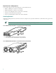
Required Tools and Equipment You need the following tools and equipment to rack-mount the chassis: • Number 2 Phillips screwdriver (not included) • Medium flat-blade screwdriver (not included) • Screws for attaching the chassis to the rack (not included) • Standard rack-mount brackets (included) • Screws for attaching the brackets to the chassis (included) Attaching Brackets Attach the mounting brackets to the chassis as shown, using the screws provided.
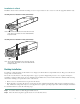
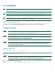
Installation in a Rack Install the chassis in the rack. Rack-mounting screws are not provided. Use two screws for each side (supplied with the rack). 35659 Installing the Cisco AS5350 in a Rack (19-Inch Rack) Note: The second bracket attaches to the rack at the other side of the chassis. The chassis can also be installed with the front panel forward. 29034 Installing the Cisco AS5400 in a Rack (19-Inch Rack) Note: The second bracket attaches to the rack at the other side of the chassis.
Step 3 Peel the rubber feet off the black adhesive strip and place them adhesive-side down at each corner of the underside of the chassis. Step 4 Place the universal gateway top-side up on a flat, smooth, secure surface. Caution Do not place anything on top of the universal gateway that weighs more than 10 lb (4.5 kg). Excessive weight on top could damage the chassis.
3 Install Modules Note The information in this document applies to the Cisco AS5350, Cisco AS5400, and Cisco AS5400HPX universal gateways. Note Unless specifically noted, all references to the Cisco AS5400 also apply to the Cisco AS5400HPX. Note Cisco AS5350 and Cisco AS5400 come with carrier cards and DFCs already installed. If the required dial feature cards are already installed, proceed to the “Connect Cables” section on page 14.
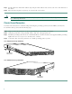
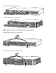
36004 Install the Carrier Card in the Cisco AS5350 37161 Install the Carrier Card in the Cisco AS5400 Step 4 Align the captive screws with their holes, and seat the card completely. Step 5 Tighten the two captive screws to secure the carrier card to the chassis.
Step 6 If the carrier card has a blank DFC slot, install a blank cover over the open DFC slot to ensure proper airflow inside the chassis. 36033 Blank DFC Cover Step 7 For AC powered units, reconnect the AC power cord. For DC powered units, reinstate power at the circuit breaker. For more information on the AC and DC power supplies, refer to the chassis installation guide. To access the chassis guide see the “Documents, Equipment, and Tools” section on page 2. Step 8 Reconnect all interface cables.
To install a DFC, follow these steps: Step 1 Attach an ESD-preventive wrist strap. Step 2 Slide the DFC into the slot until the connector pins make contact with the carrier card backplane connector. Installing a DFC in a Cisco AS5350 1 Rx Tx 36816 2 PRI 0 ACT OK 37165 Installing a DFC in a Cisco AS5400 Step 3 Align the captive screws with their holes, and seat the card completely. Step 4 Tighten the screws to secure the DFC to the chassis.
37170 Tighten the Captive Screws on the Cisco AS5400 Captive screw Step 5 Captive screw Check the card LEDs to verify that the card is working properly. The following table summarizes the LED function for the trunk and port DFCs. Dial Feature Card LEDs DFC LED State Description T1 or E1 DFC ACTIVITY (ACT) Fast flicker (Green) Indicates DFC is up and running. Slow flicker (Green) Indicates DFC is not yet fully functional.
Dial Feature Card LEDs (continued) DFC LED State Description T3 DFC ACTIVITY (ACT) Fast flicker Indicates DFC is up and running. Slow flicker Indicates DFC is not yet fully functional. On (Green) The CT3 DFC passed initial power-up diagnostics tests and is operating normally. Yellow The CT3 DFC is not functioning. See the console for messages. Off Indicates that all calls associated with the DFC are shut down and it is safe to remove the card with the system powered on.
System Management and Power Connections The connections described here provide electrical power and management access. For cable pinouts, see the chassis and card installation guides for the Cisco AS5350 and Cisco AS5400. You can access these documents at Cisco Product Documentation > Access Servers and Access Routers > Access Servers > Cisco AS5350 or Cisco AS5400 > Hardware Installation Documents for Cisco AS5350 or Cisco AS5400.
Step 1 Connect the terminal to the console port using an RJ-45 rollover cable and an RJ-45-to-DB-25 or RJ-45-to-DB-9 adapter. The adapters provided are labeled TERMINAL. The adapters and the rollover cable are included in the accessory kit that ships with the universal gateway.
Step 2 Configure your terminal or PC terminal emulation software for 9600 baud, 8 data bits, no parity, and 2 stop bits. To configure the console port, refer to the Cisco AS5350 and Cisco AS5400 Universal Gateway Software Configuration Guide. Connect to Ethernet Network • Connect the universal gateway to an Ethernet network by using a straight-through RJ-45-to-RJ-45 Ethernet cable to connect the Fast Ethernet port to an Ethernet hub.
Connect to a WAN Warning The telecommunications lines must be disconnected 1) before unplugging the main power connector and/or 2) while the housing is open. To see translations of the warnings that appear in the publication, refer to the Regulatory Compliance and Safety Information document that accompanied this device. Warning Hazardous network voltages are present in WAN ports regardless of whether power to the router is OFF or ON. To avoid electric shock, use caution when working near WAN ports.
You can connect the Cisco AS5350 and Cisco AS5400 to a WAN in the following ways: • Connect each T1/PRI port to an RJ-45 jack with a straight-through RJ-45 to RJ-45 cable.
6 7 P P 4 5 P P 2 3 P P 1 P P 0 30848 Connecting 8-Port DFC on Cisco AS5400 to RJ-45 Jack T1/E1 8 PRI connector Straight-through RJ-45-to-RJ-45 cable Note RJ-45 jack For other T1 cabling options, see the card installation guide for the Cisco AS5350 and Cisco AS5400. You can access this document at Cisco Product Documentation > Access Servers and Access Routers > Access Servers > Cisco AS5350 or Cisco AS5400 > Hardware Installation Documents for Cisco AS5350 or Cisco AS5400.
35673 Connecting 2-Port or 4-Port DFC on Cisco AS5350 to RJ-45 Jack RJ-45 jack E1 cable 6 7 P P 4 5 P P 2 3 P P 0 P P 1 56058 Connecting 8-Port DFC on Cisco AS5350 to RJ-45 Jack T1/E1 8 PRI connector E1 cable RJ-45 jack 21
6 7 P P 4 5 P P 2 3 P P 0 P P 1 30847 Connecting 8-Port DFC on Cisco AS5400 to RJ-45 Jack T1/E1 8 PRI connector E1 cable RJ-45 jack • Connect each T3 DFC to a T3 CSU/DSU with two 75-ohm BNC cables 62177 Connecting T3 DFC on Cisco AS5350 to T3 CSU/DSU T3 DFC T3 cables T3 CSU/DSU BNC connectors 22
62178 Connecting T3 DFC on Cisco AS5400 to T3 CSU/DSU T3 DFC T3 cables T3 CSU/DSU BNC connectors • Connect a synchronous serial port to a modem or a CSU/DSU with a serial transition cable. 35675 Connecting Serial Port on Cisco AS5350 to CSU/DSU Synchronous serial port (DB-26) Internet CSU/DSU or other DCE or DTE Serial transition cable EIA/TIA-232, EIA/TIA-449, EIA/TIA-530A, EIA/TIA-530, V.35, or X.
30846 Connecting Serial Port on Cisco AS5400 to CSU/DSU Synchronous serial port (DB-26) Internet CSU/DSU or other DCE or DTE Serial transition cable EIA/TIA-232, EIA/TIA-449, EIA/TIA-530A, EIA/TIA-530, V.35, or X.21 connector • Use a coaxial cable to connect a timing signal generator (TSG) to the BITS port. The BITS port is used for external clocking.
To connect an alarm device to the alarm port, follow this procedure: Note The alarm connector is a 3-wire connector that plugs into a receptacle in the rear of the chassis. The connector is provided in the accessory kit that ships with the universal gateway. Step 1 Insert the three-pin alarm port connector (included in the accessory kit) into the alarm port terminal block. Step 2 Strip a minimum 1/4 in. (0.625 cm) off the wire insulation to connect the stranded wires to the alarm connector.
Alarm Pinouts Pin1 Description 1 Normally open 2 Pole 3 Normally closed 1. The pins are numbered from left to right (facing the back of the chassis), starting with pin 1. Connect AC Power Step 1 Connect the black power cord to the receptacle on the power supply at the rear of the universal gateway. 35678 Connecting AC Power Cord to Cisco AS5350 Single Power Supply Power switch Note For the Cisco AS5350 redundant power supply, use the special power cable that came with your universal gateway.
Connecting AC Power Cord to Cisco AS5400 30851 Power switch Step 2 Connect the other end of the power cord to the electrical outlet. Step 3 If your universal gateway has a second power supply installed, repeat Step 1 and Step 2 for the second power supply. Connect DC Power Warning A readily accessible two-poled disconnect device must be incorporated in the fixed wiring.
Step 1 Warning Step 2 Warning Remove power from the DC circuit. Before performing any of the following procedures, ensure that power is removed from the DC circuit. To ensure that all power is OFF, locate the circuit breaker on the panel board that services the DC circuit, switch the circuit breaker to the OFF position, and tape the switch handle of the circuit breaker in the OFF position.
Cisco AS5350 DC Power Supply Connections—Redundant Power Supply To DC source DC connector Power switch 82637 A- A+ B- B+ Ground Source A - NEG Source B - RTN Source A - RTN Source B - NEG Cisco AS5400 DC Power Supply Connections Mounting screw Strain-relief clamps Mounting screw IN OK LEDs DC OK Terminal block OTF On/off switch IN OK LEDs DC OK Terminal block 31628 OTF Mounting screw Strain-relief clamps Step 3 Strip off a quarter of an inch (1/4 in. [0.
Note If you are installing a redundant power supply in the Cisco AS5350, you should attach appropriate sized spade terminals to the stripped ends of the ground and input wires. Step 4 Install the safety grounds (green wire) into the terminal block ground connectors and tighten the locking screws. Ensure that no bare wire is exposed. Note For central office installations, we recommend using a copper 6 AWG green ground wire with one end connected to reliable earth.
Power-Up Procedure Perform this procedure to power up your Cisco universal gateway and verify that it goes through its initialization and self-test. When this is finished, the Cisco universal gateway is ready to configure. Note To view the boot sequence through a terminal session, you must have a console connection to the Cisco universal gateway before it powers on. To connect to the console, refer to the “Connect a Console Terminal” section on page 15. Move the power switch to the ON position.
PLD/ISP Version 1.0, Manufacture Date 20-Jul-2000. Processor 0x14, MAC Address 0x0142B35F36 Backplane HW Revision 1.0, Flash Type 5V 2 FastEthernet/IEEE 802.3 interface(s) 2 Serial network interface(s) 60 terminal line(s) 2 Channelized T1/PRI port(s) 512K bytes of non-volatile configuration memory. 32768K bytes of processor board System flash (Read/Write) 8192K bytes of processor board Boot flash (Read/Write) Note If the rommon 1> prompt appears, your system has booted in ROM monitor mode.
Basic management setup configures only enough connectivity for management of the system. Extended setup will ask you to configure each interface on the system. Would you like to enter basic management setup? [yes/no]: no Step 3 When the following message appears, press Return to see the current interface summary: First, would you like to see the current interface summary? [yes]: Any interface listed with OK? value “NO” does not have a valid configuration Interface Async1/00 Async1/01 . . .
Async lines accept incoming modems calls. If you will have users dialing in via modems, configure these lines.
Operate in full-duplex mode? [no]: Operate at 100 Mbps speed? [yes]: Configure IP on this interface? [yes]: IP address for this interface [X.X.X.X]: 172.22.50.10 Subnet mask for this interface [255.255.0.0] : 255.255.255.128 Class B network is 172.22.0.
Step 7 Create a secret password. This password provides access to privileged EXEC mode. Substitute your enable secret password for guessme. Gateway(config)# enable secret guessme Step 8 Enable password encryption. When password encryption is enabled, the encrypted form of the password is displayed when a show configuration command is entered. You cannot recover a lost encrypted password.
Gateway con0 is now available Press RETURN to get started. Gateway> enable Password: Gateway# show privilege Current privilege level is 15 Gateway# Configuring Local AAA Security Configure authentication, authorization, and accounting (AAA) to perform log in authentication by using the local username database. The login keyword authenticates EXEC shell users. Additionally, configure PPP authentication to use the local database if the session was not already authenticated by login.
Tip To save the gateway configuration, save it to NVRAM. Refer to the “Saving Configuration Changes” section on page 57. Note For comprehensive information about how to implement a Cisco AAA-based security environment, see the relevant documents at Cisco Product Documentation > Network Security > Cisco IOS Technology-Specific Security Features. Configure Basic Dial Access To commission a basic dial access service perform the following tasks: • Create two loopback interfaces.
Step 4 Verify that the Fast Ethernet interface is up. Ping the default gateway to verify this. Gateway# ping 172.28.186.49 Type escape sequence to abort. Sending 5, 100-byte ICMP Echos to 172.28.186.49, timeout is 2 seconds: .!!!! Success rate is 80 percent (4/5), round-trip min/avg/max = 1/1/4 ms Tip To save the gateway configuration, save it to NVRAM.
Step 5 Return to privileged EXEC mode: Gateway(config-if)# Ctrl-Z Gateway# To save the gateway configuration, save it to NVRAM. Refer to the “Saving Configuration Changes” section on page 57.
Configuring a Channelized T1 or E1 DFC This section shows how to configure channelized T1 or E1. On a Cisco AS5350 or Cisco AS5400, you can allocate the available channels for channelized E1 and T1 in the following ways: • All channels can be configured to support ISDN PRI. • If you are not running ISDN PRI, all channels can be configured to support robbed-bit signaling (also known as channel-associated signaling). • All channels can be configured in a single channel group.
Step 6 Return to privileged EXEC mode: Gateway(config-controller)# Ctrl-Z Gateway# To save the gateway configuration, save it to NVRAM. Refer to the “Saving Configuration Changes” section on page 57. Tip Verify To verify that your controller is up and running and that no alarms have been reported: • Enter the show controller command and specify the controller type, slot, and port numbers: Gateway# show controller t1 1/7 T1 1/7 is up. No alarms detected.
Use the enable command and password to enter privileged EXEC mode. You are in privileged EXEC mode when the prompt changes to Gateway#. Step 1 Gateway> enable Password: password Gateway# Enter global configuration mode. You are in global configuration mode when the prompt changes to Gateway(config)#. Step 2 Gateway# configure terminal Enter configuration commands, one per line. End with CNTL/Z. Gateway(config)# Enter controller configuration mode to configure your T3 controller for slot 1 port 0.
0 Line Code Violations, 0 P-bit Coding Violation 0 C-bit Coding Violation, 0 P-bit Err Secs 0 P-bit Severely Err Secs, 0 Severely Err Framing Secs 0 Unavailable Secs, 0 Line Errored Secs 0 C-bit Errored Secs, 0 C-bit Severely Errored Secs Total Data (last 32 15 minute intervals): 0 Line Code Violations, 0 P-bit Coding Violation, 0 C-bit Coding Violation, 0 P-bit Err Secs, 0 P-bit Severely Err Secs, 0 Severely Err Framing Secs, 0 Unavailable Secs, 0 Line Errored Secs, 0 C-bit Errored Secs, 0 C-bit Severely E
ISDN Switch Types Area Keyword Switch Type Australia primary-ts014 Australia PRI switches Europe primary-net5 European, New Zealand, and Asia ISDN PRI switches (covers the Euro-ISDN E-DSS1 signaling system and is European Telecommunication Standards Institute or ETSI-compliant) Japan primary-ntt Japanese ISDN PRI switches None none No switch defined North America primary-4ess AT&T 4ESS switch type for the United States primary-5ess AT&T 5ESS switch type for the United States primary-dms
Note For CE1 ISDN PRI—If you do not specify the time slots, the specified controller is configured for 30 B channels and 1 D channel. B channel numbers range 1 to 31; channel 16 is the D channel for E1. Corresponding serial interface numbers range 0 to 30. In commands, the D channel is interface serial slot/port:15—for example, interface serial 1/0:15. Step 6 Return to privileged EXEC mode: Gateway(config-controller)# Ctrl-Z Gateway# To save the gateway configuration, save it to NVRAM.
Framing is ESF, Line Code is B8ZS, Clock Source is Line.
controller T1 1/0:11 framing esf channel-group 20 timeslots ! controller T1 1/0:12 framing esf channel-group 20 timeslots ! controller T1 1/0:13 framing esf channel-group 20 timeslots ! controller T1 1/0:14 framing esf channel-group 20 timeslots ! controller T1 1/0:15 framing esf channel-group 20 timeslots 1-24 speed 64 1-24 speed 64 1-24 speed 64 1-24 speed 64 1-24 speed 64 If you are having trouble: • If the Layer 1 Status is “Deactivated,” make sure that the cable connection is not loose or disconn
Relationship of ISDN PRI Components for T1 Time slot number B B B B • • • • • B B B D 1 2 3 4 • • • • • 21 22 23 24 S0:0 S0:1 S0:2 S0:3 • • • • • S0:20 S0:21 S0:22 S0:23 (data channel) (data channel) (data channel) (data channel) (data channel) (data channel) (data channel) (signaling channel) Note Logical contents of a PRI interface 35765 Channel type Virtual serial interface number When you configure your CT1 controller for an Non-Facility Associated Signaling (NFAS) backup D channel, a serial
Step 6 Return to privileged EXEC mode: Gateway(config-if)# ctrl-z Gateway# To save the gateway configuration, save it to NVRAM. Refer to the “Saving Configuration Changes” section on page 57. Tip Verify To verify your D channel configuration: • Enter the show interface serial command and make sure that the line protocol is up and that you are using the correct IP interface. Also, make sure that excessive errors are not being reported.
SPE Firmware SPE firmware is automatically downloaded to a universal port DFC from the Cisco AS5350 or Cisco AS5400 when you boot the system for the first time or when you insert a universal port DFC while the system is operating. When you insert DFCs while the system is operating, the Cisco IOS image recognizes the cards and downloads the required firmware to the cards. The SPE firmware image is bundled with the universal gateway Cisco IOS image.
Step 2 Enter global configuration mode. You are in global configuration mode when the prompt changes to Gateway(config)#. Gateway# configure terminal Enter configuration commands, one per line. End with CNTL/Z. Gateway(config)# Step 3 Specify the country to set the DFC parameters (including country code and encoding). This setting is applied at the system level. All DFCs use the same country code.
Total ports: 108, in use ports: 0, disabled ports: 0, free ports: 108 Total active calls: modem 0, voice 0, digital 0, fax-relay SPE# 4/00 4/01 4/02 4/03 4/04 . . .
Dial Feature Card Ports The TDM bus can be synchronized with any DFC cards. On the CT1/CE1 DFCs, each port receives the clock from the T1/E1 line. The CT3 DFC uses an M13 multiplexer to receive the DS1 clock. Each port on each DFC trunk slot has a default clock priority. Also, clock priority is configurable through the dial-tdm-clock priority CLI command. External Clock The TDM bus can be synchronized with an external clock source that can be used as an additional network reference.
To save the gateway configuration, save it to NVRAM. Refer to the “Saving Configuration Changes” section on page 57.
• Verify your TDM clock history by using the show tdm clocks command (this example is for CT3): Gateway# show tdm clocks Primary Clock: -------------System primary is slot 7 ds3_port 0 ds1_port 1 of priority 1 TDM Bus Master Clock Generator State = NORMAL Backup clocks for primary: Source Slot Port DS3-Port Priority Status State ------------------------------------------------------------Trunk 7 8 YES 214 Good Default Trunk 7 9 YES 215 Good Default Trunk cards controllers clock health information ----------
Slot Type 7 6 5 4 3 2 1 0 2 T1 B B B B G G G G CLOCK CHANGE HISTORY CLOCK Event Freerun Change in CLI configuration Gateway# Time 23:27:25 UTC Tue Nov 30 1999 • Verify your BITS clock selection by using the show tdm clocks command: Gateway# show tdm clocks Primary Clock: System primary is external with priority 1 TDM Bus Master Clock Generator State = NORMAL Backup clocks for primary: Source Slot Port DS3-Port Priority Status Trunk 2 0 NO 204 Good Trunk 2 1 NO 205 Good Trunk cards controllers clock health
• Establish a working IP network. For more information about configuring IP, refer to the appropriate release of the Cisco IOS IP Configuration Guide. You can access this document at Cisco Product Documentation > Cisco IOS Software Configuration > Cisco IOS Software Release you are using > Configuration Guides and Command References. • Complete basic configuration for the universal gateway, which includes, as a minimum, the following tasks: – Complete your company’s dial plan.
You can access these documents at Cisco Product Documentation > Cisco IOS Software Configuration > Cisco IOS Software Release you are using > Configuration Guides and Command References. For new features associated with a software release: New feature documentation for the Cisco IOS software release installed on your Cisco gateway. You can access these documents at Cisco Product Documentation > Cisco IOS Software Configuration > Cisco IOS Software Release you are using > New Feature Documentation.
You can access the Cisco website at this URL: http://www.cisco.com International Cisco web sites can be accessed from this URL: http://www.cisco.com/public/countries_languages.shtml Documentation CD-ROM Cisco documentation and additional literature are available in a Cisco Documentation CD-ROM package, which may have shipped with your product. The Documentation CD-ROM is updated monthly and may be more current than printed documentation.
Cisco.com Cisco.com offers a suite of interactive, networked services that let you access Cisco information, networking solutions, services, programs, and resources at any time, from anywhere in the world. Cisco.
Before calling, please check with your network operations center to determine the level of Cisco support services to which your company is entitled: for example, SMARTnet, SMARTnet Onsite, or Network Supported Accounts (NSA). When you call the center, please have available your service agreement number and your product serial number.
Corporate Headquarters Cisco Systems, Inc. 170 West Tasman Drive San Jose, CA 95134-1706 USA www.cisco.com Tel: 408 526-4000 800 553-NETS (6387) Fax: 408 526-4100 European Headquarters Cisco Systems International BV Haarlerbergpark Haarlerbergweg 13-19 1101 CH Amsterdam The Netherlands www-europe.cisco.com Tel: 31 0 20 357 1000 Fax: 31 0 20 357 1100 Americas Headquarters Cisco Systems, Inc. 170 West Tasman Drive San Jose, CA 95134-1706 USA www.cisco.