Cisco Model DPC3010 and EPC3010 DOCSIS 3.0 8x4 Cable Modem User Guide In This Document IMPORTANT SAFETY INSTRUCTIONS ............................................................... 2 FCC Compliance ......................................................................................................... 7 CE Compliance............................................................................................................ 8 Introducing the DPC3010 and EPC3010 ......
IMPORTANT SAFETY INSTRUCTIONS IMPORTANT SAFETY INSTRUCTIONS Notice to Installers The servicing instructions in this notice are for use by qualified service personnel only. To reduce the risk of electric shock, do not perform any servicing other than that contained in the operating instructions, unless you are qualified to do so.
IMPORTANT SAFETY INSTRUCTIONS Mitteilung für CATV-Techniker Die in dieser Mitteilung aufgeführten Wartungsanweisungen sind ausschließlich für qualifiziertes Fachpersonal bestimmt. Um die Gefahr eines elektrischen Schlags zu reduzieren, sollten Sie keine Wartungsarbeiten durchführen, die nicht ausdrücklich in der Bedienungsanleitung aufgeführt sind, außer Sie sind zur Durchführung solcher Arbeiten qualifiziert.
IMPORTANT SAFETY INSTRUCTIONS IMPORTANT SAFETY INSTRUCTIONS 1) Read these instructions. 2) Keep these instructions. 3) Heed all warnings. 4) Follow all instructions. 5) Do not use this apparatus near water. 6) Clean only with dry cloth. 7) Do not block any ventilation openings. Install in accordance with the manufacturer's instructions. 8) Do not install near any heat sources such as radiators, heat registers, stoves, or other apparatus (including amplifiers) that produce heat.
IMPORTANT SAFETY INSTRUCTIONS Ground the Product WARNING: Avoid electric shock and fire hazard! If this product connects to coaxial cable wiring, be sure the cable system is grounded (earthed). Grounding provides some protection against voltage surges and built-up static charges. Protect the Product from Lightning In addition to disconnecting the AC power from the wall outlet, disconnect the signal inputs.
IMPORTANT SAFETY INSTRUCTIONS Service Warnings WARNING: Avoid electric shock! Do not open the cover of this product. Opening or removing the cover may expose you to dangerous voltages. If you open the cover, your warranty will be void. This product contains no user-serviceable parts. Check Product Safety Upon completion of any service or repairs to this product, the service technician must perform safety checks to determine that this product is in proper operating condition.
FCC Compliance FCC Compliance United States FCC Compliance This device has been tested and found to comply with the limits for a Class B digital device, pursuant to part 15 of the FCC Rules. These limits are designed to provide reasonable protection against such interference in a residential installation. This equipment generates, uses, and can radiate radio frequency energy. If not installed and used in accordance with the instructions, it may cause harmful interference to radio communications.
CE Compliance CE Compliance Declaration of Conformity with Regard to the EU Directive 1999/5/EC (R&TTE Directive) This declaration is only valid for configurations (combinations of software, firmware and hardware) supported or provided by Cisco Systems for use within the EU. The use of software or firmware not supported or provided by Cisco Systems may result in the equipment no longer being compliant with the regulatory requirements.
CE Compliance The following standards were applied during the assessment of the product against the requirements of the Directive 1999/5/EC: EMC: EN 55022 and EN 55024 EN 61000-3-2 and EN 61000-3-3 Safety: EN 60950-1 This product conforms to the following European directives: -2006/95/EC -1999/5/EC -2004/108/EC 20090312 CE_Modem/EMTA 4030802 Rev C 9
Introducing the DPC3010 and EPC3010 Introducing the DPC3010 and EPC3010 Welcome to the exciting world of high-speed Internet access. You have acquired one of the fastest cable modems available on the market today. Your new Cisco® Model DPC3010 or Model EPC3010 DOCSIS® 3.0 Cable Modem offers high-end performance and superb reliability at data rates up to eight times that of conventional DOCSIS 2.0 (DPC3010) and EuroDOCSIS™ (EPC3010) cable modems.
Introducing the DPC3010 and EPC3010 Design and Function Color-coded connectors and cables for easy installation and setup Features Plug and Play operation for easy set up and installation Uses an attractive compact design and a versatile orientation to lie flat or stand vertically on a desktop or shelf, or mount easily on a wall LED status indicators on the front panel provide an informative and easy-tounderstand display that indicates the cable modem status and real-time data transmission activity
What's in the Carton? What's in the Carton? When you receive your cable modem, you should check the equipment and accessories to verify that each item is in the carton and that each item is undamaged. The carton typically contains the following items: One Cisco Model DPC3010 or EPC3010 DOCSIS 3.0 Cable Modem One power adapter with power cord One Ethernet cable (CAT5/RJ-45) (Ethernet cable may not be provided with all modems.) One USB cable (USB cable may not be provided with all modems.
Front Panel Description Front Panel Description The front panel of your cable modem provides LED status indicators that indicate how well and at what state your cable modem is operating. After the cable modem is successfully registered on the network, the POWER and ONLINE LED status indicators illuminate continuously to show that the cable modem is active and fully operational. See Front Panel LED Status Indicator Functions (on page 32) for more information on front panel LED status indicator functions.
Back Panel Description Back Panel Description The following illustration describes the back panel components of the DPC3010 and EPC3010 DOCSIS 3.0 cable modems. 1 POWER—Connects the cable modem to the 12 VDC output of the AC power adapter that is provided with your cable modem. Only use the AC power adapter and power cord that is provided with your cable modem 2 ETHERNET—Bridged RJ-45 Gigabit Ethernet port connects to the Ethernet port on your PC.
What Are the System Requirements for Internet Service? What Are the System Requirements for Internet Service? To ensure that your cable modem operates efficiently for high-speed Internet service, verify that all of the Internet devices on your system meet or exceed the following minimum hardware and software requirements. Note: You will also need an active cable input line and an Internet connection.
How Do I Set Up My High-Speed Internet Access Account? How Do I Set Up My High-Speed Internet Access Account? Before you can use your cable modem, you need to have a high-speed Internet access account. If you do not have a high-speed Internet access account, you need to set up an account with your local service provider. Choose one of the two options in this section.
Where Is the Best Location for My Cable Modem? Where Is the Best Location for My Cable Modem? The ideal location for your cable modem is where it has access to outlets and other devices. Think about the layout of your home or office, and consult with your service provider to select the best location for your cable modem. Read this user guide thoroughly before you decide where to place your cable modem.
How Do I Mount the Cable Modem on the Wall? How Do I Mount the Cable Modem on the Wall? Before You Begin Before you begin, choose an appropriate mounting place. The wall can be made of cement, wood, or drywall. The mounting location should be free of obstructions on all sides, and the cables should be able to easily reach the cable modem without strain. Leave sufficient clearance between the bottom of the cable modem, and any flooring or shelving underneath, to allow access to cabling.
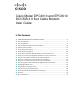
How Do I Mount the Cable Modem on the Wall? Location and Dimensions of the Wall-Mounting Slots The following illustration shows the location and dimensions of the wall-mounting slots on the bottom of the modem. Use the information on this page as a guide for mounting your modem to the wall. Important: This graphic is not drawn to scale.
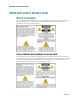
How Do I Mount the Cable Modem on the Wall? Wall Mounting Instructions Complete these steps to mount the modem to the wall. 1 Locate the place where you want to mount the modem to the wall. 2 Hold the modem level against the wall and at an angle so that the screw hole mounting guides are facing up and against the wall. 3 Lay a pencil, pen, or other marking tool into each guide and mark the place on the wall where you want to drill the mounting holes.
How Do I Connect My Devices to Use the Internet? How Do I Connect My Devices to Use the Internet? You can use your cable modem to access the Internet, and you can share that Internet connection with other Internet devices in your home or office. Sharing one connection among many devices is called networking. Connecting and Installing Internet Devices You must connect and install your cable modem to access the Internet. Professional installation may be available.
Connecting the Cable Modem for High-Speed Data Service Connecting the Cable Modem for High-Speed Data Service The following installation procedure ensures proper setup and configuration for the cable modem. 1 Choose an appropriate and safe location to install the cable modem (close to a power source, an active cable connection, your PC—if using high-speed Internet, and your telephone lines—if using VoIP).
Connecting the Cable Modem for High-Speed Data Service 5 Locate the AC power adapter provided with your cable modem. Insert the barrel-shaped DC power connector (attached by a thin pair of wires to the AC power adapter) into the black POWER connector on the back of the modem. Then, plug the AC power cord into an AC outlet to power up the cable modem. The cable modem will perform an automatic search to locate and sign on to the broadband data network. This process typically takes up to 2-5 minutes.
Installing USB Driver Installing USB Driver To install USB drivers, your PC must be equipped with a USB network interface and a Microsoft Windows 2000 or Windows XP operating system. This section contains instructions for installing the USB drivers for the cable modem. The USB drivers needed for your cable modem are located in the Roof directory of the Installation CD provided with your cable modem. Note: If you are not using the USB interface, skip this section.
Installing USB Driver Installing USB Drivers on Windows XP Systems 1 Insert the USB Cable Modem Driver Installation Disk into the CD-ROM drive of your PC. 4030802 Rev C 2 Wait until the ONLINE LED status indicator on the front panel of the cable modem illuminates solid green. 3 Select Install from a list or specific location (Advanced) in the Found New Hardware Wizard window, and then click Next.
Frequently Asked Questions Frequently Asked Questions Q. How Do I Configure TCP/IP Protocol? A. To configure TCP/IP protocol, you need to have an Ethernet Network Interface Card (NIC) with TCP/IP communications protocol installed on your system. TCP/IP is a communications protocol used to access the Internet. This section contains instructions for configuring TCP/IP on your Internet devices to operate with the cable modem in Microsoft Windows or Macintosh environments.
Frequently Asked Questions Configuring TCP/IP on Windows 2000 Systems 1 Click Start, select Settings, and choose Network and Dial-up Connections. 2 Double-click the Local Area Connection icon in the Network and Dial-up Connections window. 3 Click Properties in the Local Area Connection Status window. 4 Click Internet Protocol (TCP/IP) in the Local Area Connection Properties window, and then click Properties.
Frequently Asked Questions 3 Click Advanced in the User Mode window, and then click OK. 4 Click the Up/Down selector arrows located to the right of the Connect Via section of the TCP/IP window, and then click Using DHCP Server. 5 Click Options in the TCP/IP window, and then click Active in the TCP/IP Options window. Note: Make sure that the Load only when needed option is unchecked. 6 Verify that the Use 802.3 option located in the upper-right corner of the TCP/IP window is unchecked.
Frequently Asked Questions Renewing the IP Address on Windows NT, 2000, or XP Systems 1 Click Start, and then click Run. The Run window opens. 2 Type cmd in the Open field and click OK. A window with a command prompt opens. 3 Type ipconfig/release at the C:/ prompt and press Enter. The system releases the IP address. 4 Type ipconfig/renew at the C:/ prompt and press Enter. The system displays a new IP address. 5 Click the X in the upper-right corner of the window to close the Command Prompt window.
Frequently Asked Questions Q. Can I run more than one device on the modem? A. Yes. If your service provider permits, a single cable modem can support up to 63 Ethernet devices utilizing user-supplied Ethernet hubs or routers that you can purchase at your local PC or office supply retailer. Another user at your location can simultaneously connect to the USB port on the cable modem. Contact your service provider for further assistance.
Tips for Improved Performance Tips for Improved Performance Check and Correct If your cable modem does not perform as expected, the following tips may help. If you need further assistance, contact your service provider. Verify that the plug to your cable modem AC power is properly inserted into an electrical outlet. Verify that your cable modem AC power cord is not plugged into an electrical outlet that is controlled by a wall switch.
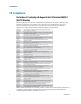
Front Panel LED Status Indicator Functions Front Panel LED Status Indicator Functions Initial Power Up, Calibration, and Registration The following chart illustrates the sequence of steps and the corresponding appearance of the cable modem front panel LED status indicators during power-up, calibration, and registration on the network. Use this chart to troubleshoot the power up, calibration, and registration process of your cable modem.
Front Panel LED Status Indicator Functions Normal Operations The following table illustrates the appearance of the cable modem front panel LED status indicators during normal operations.
Front Panel LED Status Indicator Functions Special Conditions The following table describes the appearance of the cable modem front panel LED status indicators during special conditions to show that you have been denied network access.
Notices Notices Trademarks Cisco and the Cisco logo are trademarks or registered trademarks of Cisco and/or its affiliates in the U.S. and other countries. A listing of Cisco's trademarks can be found at www.cisco.com/go/trademarks. DOCSIS is a registered trademark of Cable Television Laboratories, Inc. EuroDOCSIS, EuroPacketCable, and PacketCable are trademarks of Cable Television Laboratories, Inc. Other third party trademarks mentioned are the property of their respective owners.
For Information For Information If You Have Questions If you have technical questions, call Cisco Services for assistance. Follow the menu options to speak with a service engineer.
Cisco Systems, Inc. 5030 Sugarloaf Parkway, Box 465447 Lawrenceville, GA 30042 678 277-1120 800 722-2009 www.cisco.com Cisco and the Cisco logo are trademarks or registered trademarks of Cisco and/or its affiliates in the U.S. and other countries. A listing of Cisco's trademarks can be found at www.cisco.com/go/trademarks. Third party trademarks mentioned are the property of their respective owners. The use of the word partner does not imply a partnership relationship between Cisco and any other company.