Cisco Model DPC3827 and EPC3827 DOCSIS 3.0 8x4 Wireless Residential Gateway User Guide In This Document IMPORTANT SAFETY INSTRUCTIONS ...............................................................ii Introduction ............................................................................................................... 12 What's In the Carton? ...............................................................................................
IMPORTANT SAFETY INSTRUCTIONS IMPORTANT SAFETY INSTRUCTIONS Notice to Installers The servicing instructions in this notice are for use by qualified service personnel only. To reduce the risk of electric shock, do not perform any servicing other than that contained in the operating instructions, unless you are qualified to do so.
Mitteilung für CATV-Techniker Die in dieser Mitteilung aufgeführten Wartungsanweisungen sind ausschließlich für qualifiziertes Fachpersonal bestimmt. Um die Gefahr eines elektrischen Schlags zu reduzieren, sollten Sie keine Wartungsarbeiten durchführen, die nicht ausdrücklich in der Bedienungsanleitung aufgeführt sind, außer Sie sind zur Durchführung solcher Arbeiten qualifiziert.
) Follow all instructions. 5) Do not use this apparatus near water. 6) Clean only with dry cloth. 7) Do not block any ventilation openings. Install in accordance with the manufacturer's instructions. 8) Do not install near any heat sources such as radiators, heat registers, stoves, or other apparatus (including amplifiers) that produce heat. 9) Do not defeat the safety purpose of the polarized or grounding-type plug. A polarized plug has two blades with one wider than the other.
Eliminate AC Power/Mains Overloads WARNING: Avoid electric shock and fire hazard! Do not overload AC power/mains, outlets, extension cords, or integral convenience receptacles. For products that require battery power or other power sources to operate them, refer to the operating instructions for those products. Provide Ventilation and Select a Location Remove all packaging material before applying power to the product.
Protect the Product When Moving It Always disconnect the power source when moving the apparatus or connecting or disconnecting cables.
United States FCC Compliance This device has been tested and found to comply with the limits for a Class B digital device, pursuant to part 15 of the FCC Rules. These limits are designed to provide reasonable protection against such interference in a residential installation. This equipment generates, uses, and can radiate radio frequency energy. If not installed and used in accordance with the instructions, it may cause harmful interference to radio communications.
US This system has been evaluated for RF exposure for humans in reference to ANSI C 95.1 (American National Standards Institute) limits. The evaluation was based in accordance with FCC OET Bulletin 65C rev 01.01 in compliance with Part 2.1091 and Part 15.27. The minimum separation distance from the antenna to general bystander is 7.9 inches (20 cm) to maintain compliance. Canada This system has been evaluated for RF exposure for humans in reference to Canada Health Code 6 (2009) limits.
CE Compliance Declaration of Conformity with Regard to the EU Directive 1999/5/EC (R&TTE Directive) This declaration is only valid for configurations (combinations of software, firmware and hardware) supported or provided by Cisco Systems for use within the EU. The use of software or firmware not supported or provided by Cisco Systems may result in the equipment no longer being compliant with the regulatory requirements. Note: The full declaration of conformity for this product can be found at http://www.
The following standards were applied during the assessment of the product against the requirements of the Directive 1999/5/EC: Radio: EN 300 328 EMC: EN 301 489-1 and EN 301 489-17 Safety: EN 60950 and EN 50385 The CE mark and class-2 identifier are affixed to the product and its packaging. This product conforms to the following European directives: -1999/5/EC National Restrictions This product is for indoor use only. France For 2.
Antennas Use only the antenna supplied with the product.
Introduction Introduction Welcome to the exciting world of high-speed Internet service. Your new Cisco® Model DPC3827 DOCSIS® 8x4 3.0 or EPC3827 EuroDOCSIS™ Wireless Residential Gateway is a high-performance home gateway that combines a cable modem, router, wireless access point, and MoCA™ in a single device for both the home and small office.
Introduction Design and Function Simplified self-install using intuitive webpage design for user-friendly setup and management DOCSIS-5 compliant LED labeling and behavior with dual-color LEDs provides a user- and technician-friendly method to check operational status and act as a troubleshooting tool TR-068 compliant color-coded interface ports and corresponding cables simplify installation and setup Attractive, compact design and versatile orientation to stand vertically, lie flat on the desktop
What's In the Carton? What's In the Carton? When you receive your wireless residential gateway, you should check the equipment and accessories to verify that each item is in the carton and that each item is undamaged. The carton contains the following items: One DPC3827 or EPC3827 Residential Gateway One Ethernet cable (CAT5/RJ-45) One power adapter (models requiring external power supply) One CD-ROM If any of these items are missing or damaged, please contact your service provider for assistance.
Front Panel Description Front Panel Description The front panel of your residential gateway provides LED status indicators that indicate how well and at what state your residential gateway is operating. See Front Panel LED Status Indicator Functions (on page 106), for more information on front panel LED status indicator functions.
Back Panel Description Back Panel Description The following illustrations show the description and function of the back panel components on the Cisco DPC3827 residential gateway. 1 POWER—Connects the residential gateway to the AC power adapter that is provided with your residential gateway CAUTION: Avoid damage to your equipment. Only use the power supply that is provided with your residential gateway.
Back Panel Description 8 RESET—A momentary pressing (1-2 seconds) of this switch reboots the EMTA. Pressing the switch for more than ten seconds first causes a reset-to-factory default of all settings and then reboots the gateway CAUTION: The Reset button is for maintenance purposes only. Do not use unless instructed to do so by your cable service provider. Doing so may cause you to lose any cable modem settings you have selected.
What Are the System Requirements for Internet Service? What Are the System Requirements for Internet Service? To ensure that your residential gateway operates efficiently for high-speed Internet service, verify that all of the Internet devices on your system meet or exceed the following minimum hardware and software requirements. Note: You will also need an active cable input line and an Internet connection.
How Do I Subscribe to High-Speed Internet Service? How Do I Subscribe to High-Speed Internet Service? Before you can use your residential gateway, you need to have a high-speed Internet access account. If you do not have a high-speed Internet access account, you need to set up an account with your local service provider. Choose one of the options in this section.
Where Is the Best Location for My DOCSIS Residential Gateway? Where Is the Best Location for My DOCSIS Residential Gateway? The ideal location for your residential gateway is where it has access to outlets and other devices. Think about the layout of your home or office, and consult with your service provider to select the best location for your residential gateway. Read this user guide thoroughly before you decide where to place your residential gateway.
How Do I Mount the Modem on a Wall? (Optional) How Do I Mount the Modem on a Wall? (Optional) You can mount the residential gateway on a wall using two wall anchors, two screws, and the mounting slots located on the unit. The modem can be mounted vertically or horizontally. Before You Begin Before you begin, choose an appropriate mounting place. The wall can be made of cement, wood, or drywall.
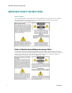
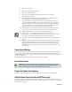
How Do I Mount the Modem on a Wall? (Optional) Mount the modem as shown in one of the following illustrations. Location and Dimensions of the Wall-Mounting Slots The following illustration shows the location and dimensions of the wall-mounting slots on the bottom of the modem. Use the information on this page as a guide for mounting your modem to the wall.
How Do I Mount the Modem on a Wall? (Optional) Mounting the Residential Gateway on a Wall 1 Using a drill with a 3/16-inch bit, drill two holes at the same height and 4 inches apart. Note: The preceding graphic illustrates the location of the mounting holes on the back of the residential gateway. 2 Are you mounting the residential gateway into a drywall or concrete surface where a wooden stud is available? If yes, go to step 3.
How Do I Connect My Gateway for Internet Service? How Do I Connect My Gateway for Internet Service? You can use your residential gateway to provide Internet access, and you can share that Internet connection with other Internet devices in your home or office. Sharing one connection among many devices is called networking. Connecting and Installing Internet Devices Professional installation may be available. Contact your local service provider for further assistance.
How Do I Connect My Gateway for Internet Service? 3 Connect the active RF coaxial cable from your service provider to the coax connector labeled CABLE on the back of the residential gateway. Note: To connect a TV, DHCT, set-top, or VCR from the same cable connection, you will need to install a cable signal splitter (not included). Always check with your service provider before using a splitter as a splitter may degrade the signal.
How Do I Configure My DOCSIS Residential Gateway? How Do I Configure My DOCSIS Residential Gateway? To configure your residential gateway, you must first access the WebWizard configuration pages. This section provides detailed instructions and procedures for accessing the WebWizard pages and for configuring your residential gateway to operate correctly. This section also presents examples and descriptions of each WebWizard configuration page.
How Do I Configure My DOCSIS Residential Gateway? 2 In the address field, enter the following IP address: 192.168.0.1. A Status DOCSIS WAN login page similar to the following page opens. 3 On the Status DOCSIS WAN page, leave the User Name and Password field blank and click Log In. The gateway opens with an Administration Management page in the forefront. You can use the Administration Management page to change your User Name and Password. At this point you are logged into the gateway.
How Do I Configure My DOCSIS Residential Gateway? Important: We highly recommend that you set up a new password to safeguard against the possibility of Internet attacks that look for devices operating with well-known or factory default user names and/or passwords. 4 On the Administration Management page, create a User Name and Password and then click Save Settings. Once you save the settings for your User Name and Password on the Administration Management page, the Setup Quick Setup page opens.
How Do I Configure My DOCSIS Residential Gateway? Select the Lan Setup tab to open the Setup Lan Setup page. Configuring Your Network Settings Use the descriptions and instructions in the following table to configure the network settings for your residential gateway. After you make your selections, click Save Settings to apply your changes or click Cancel Changes to cancel. Section Field Description Network Setup (LAN) Local IP Address Gateway IP The base IP address of the private home LAN.
How Do I Configure My DOCSIS Residential Gateway? Section Field Description Network Address Server Settings (DHCP) DHCP Server Allows you to enable or disable the DHCP server in the residential gateway. The DHCP server is used to automatically allocate IP addresses to devices as they are attached to your home network. Connected Devices Summary page Click Connected Devices Summary in the Lan Setup page. The Connected Devices Summary page opens.
How Do I Configure My DOCSIS Residential Gateway? Section Field Description Starting IP Address Displays the starting address used by the built-in DHCP server to distribute Private LAN IP addresses. Because the device default IP address of the gateway is 192.168.0.1, the starting IP address must be 192.168.0.2 or greater, but smaller than 192.168.0.253. The default Starting IP Address is 192.168.0.10.
How Do I Configure My DOCSIS Residential Gateway? Disabling DDNS (Factory Default Settings) To disable DDNS, select Disabled from the drop-down list and click Save Settings. Enabling DDNS Note: In order to use the DDNS feature, you must first set up an account and establish a URL with www.DynDNS.org. The DDNS feature will not work without a valid account. To set up a DDNS account, open your browser and enter www.DynDNS.org in the address bar. Follow the instructions on the website to set up an account.
How Do I Configure My DOCSIS Residential Gateway? Setup > Wireless QoS The following illustration is an example of the Wireless QoS (Quality of Service) page. Setup > Advanced Routing Use this page to set up the advanced routing functions such as enabling or disabling the network address translation (NAT).
How Do I Configure My DOCSIS Residential Gateway? Use the following table to configure the advanced routing settings for the residential gateway. After you make your selections, click Save Settings to apply your changes or Cancel Changes to cancel. Section Field Description Advanced Routing MTU Size MTU MTU is the Maximum Transmission Unit. The MTU size specifies the largest packet size permitted for Internet transmission.
How Do I Configure My DOCSIS Residential Gateway? 2 From the Select Set Number drop-down list, select the set number (routing table entry number) that you wish to view or configure. 3 Complete the fields on the page. 4 Click Delete This Entry to delete (clear) the entry if desired. Display Routing Table To view all the static routes you have defined, complete the following steps. 1 From the Setup page, click Advanced Routing. 2 Click Show Routing Table to display the routing table.
How Do I Configure My DOCSIS Residential Gateway? Select the Firewall tab to open the Security Firewall page. Use the descriptions and instructions in the following table to configure the firewall for your residential gateway. After you make your selections, click Save Settings to apply your changes or Cancel Changes to cancel. Section Field Description Firewall SPI Firewall Protection SPI Firewall Protection blocks Denial of Service (DoS) attacks.
How Do I Configure My DOCSIS Residential Gateway? Section Field Description Block Java and ActiveX Scripts Enables/disables java applets and ActiveX scripts. This feature helps to protect the devices in your private network from irritating or malicious Java applets that are sent, unsolicited, to devices in your private network from the Internet. These applets run automatically when they are received by a PC. Java is a programming language for websites.
How Do I Configure My DOCSIS Residential Gateway? Security > VPN Passthrough Use this page to configure Virtual Private Network (VPN) support. Enabling the settings on this page allows VPN tunnels using IPsec or PPTP protocols to pass through the gateway's firewall. Select the VPN Passthrough tab to open the Security VPN Passthrough page. Use the descriptions and instructions in the following table to configure the VPN passthrough for your residential gateway.
How Do I Configure My DOCSIS Residential Gateway? Security > VPN A Virtual Private Network (VPN) is a connection between two endpoints in different networks that allows private data to be sent securely over public networks or other private networks. This is accomplished by creating a "VPN tunnel." A VPN tunnel connects the two PCs or networks and allows data to be transmitted over the Internet as if it were on a private network.
How Do I Configure My DOCSIS Residential Gateway? Section Field Description VPN Tunnel Select Tunnel Entry Allows you to display a list of created VPN tunnels Create Button Click this button to create a new tunnel entry Delete Button Click this button to delete all settings for the selected tunnel Summary Button Click this button to display the settings and status of all enabled tunnels IPSec VPN Tunnel Allows you to enable or disable Internet Security Protocol for the VPN tunnel Tunnel Name Enter the na
How Do I Configure My DOCSIS Residential Gateway? Section Field Description Remote Secure Gateway Select the desired option, IP Addr., Any, or FQDN. If the remote gateway has a dynamic IP address, select Any or FQDN. If Any is selected, then the Gateway will accept requests from any IP address.
How Do I Configure My DOCSIS Residential Gateway? Section Field Description Select one of the following options for the key exchange method: Auto (IKE) – Encryption: The Encryption method determines the length of the key used to encrypt/decrypt ESP packets. Notice that both sides must use the same method. – Authentication: The Authentication method authenticates the Encapsulating Security Payload (ESP) packets. Select MD5 or SHA. Notice that both sides (VPN endpoints) must use the same method.
How Do I Configure My DOCSIS Residential Gateway? Section Field Description Manual – Encryption: The Encryption method determines the length of the key used to encrypt/decrypt ESP packets. Note that both sides must use the same method. – Encryption Key: This field specifies a key used to encrypt and decrypt IP traffic. Both character and hexadecimal values are acceptable in this field. Note that both sides must use the same Encryption Key.
How Do I Configure My DOCSIS Residential Gateway? Section Field Description Buttons Connect Click this button to establish a connection for the current VPN tunnel. If you have made any changes, click Save Settings to first apply your changes. Disconnect Click this button to break a connection for the current VPN tunnel. View Log Click this button to view the VPN log, which shows details of each established tunnel.
How Do I Configure My DOCSIS Residential Gateway? Number of events that have occurred Last occurrence of an event Target and source addresses You can view the following logs from this page: Access log Firewall log VPN log Parental Control log Click Clear to clear the log data.
Control Access to the Gateway Control Access to the Gateway Access Restrictions > Basic Rules Access restrictions allow you to block or allow specific kinds of Internet usage and traffic, such as Internet access, designated applications, websites, and inbound traffic during specific days and times. The Access Restrictions Basic Rules page allows you to configure parental controls on the residential gateway, and to monitor the individuals who are authorized to set parental controls.
Control Access to the Gateway Section Field Description Parental Control Basic Setup Parental Control Activation Allows you to enable or disable parental controls. To enable parental controls, select the Enable Parental Control check box and click Apply. To disable parental controls, clear the Enable Parental Control check box and click Apply.
Control Access to the Gateway Section Field Description Override the Password Password Allows you to create a password to temporarily override user access restrictions to a blocked Internet site Re-Enter Password Re-enter the same password for confirmation of the override password in the previous field Access Duration Allows you to designate an amount of time in minutes that the Override password will allow temporary access to a restricted Internet site Apply Saves all additions, edits, and changes To us
Control Access to the Gateway If the application you want to block is not listed, select User-Defined. Then, enter the port range and protocol for the service you wish to block. To remove a block, select None from the Blocked Services drop-down menu. Click the Save Settings button to save the policy settings.
Control Access to the Gateway Access Restrictions Time of Day Rules Page Description Use the descriptions and instructions in the following table to configure the time of day rules for your residential gateway. After you make your selections, click Save Settings to apply your changes or Cancel Changes to cancel. Section Field Description Tod Filter Add Allows you to add a new Time of Day access filter or rule. Enter the name of the filter and click the Add key to add the filter to the list.
Control Access to the Gateway Select the User Setup tab to open the Access Restrictions User Setup page. Access Restrictions User Setup Page Description Use the descriptions and instructions in the following table to configure the user setup for your residential gateway. After you make your selections, click Save Settings to apply your changes or Cancel Changes to cancel. Section Field Description User Configure Add User Allows you to add a new user profile.
Control Access to the Gateway Section Field Description Trusted User Check this box if the currently selected user is to be designated a trusted user. Trusted users are not subject to Internet access rules. Content Rule Select the Content Rule for the current user profile. Content Rules must first be defined by going to the Rules Configuration page. You can access the Rule Configuration page by clicking on the ―Basic Rules‖ tab on this page.
Control Access to the Gateway Select the IP Address Filtering tab to open the Access Restrictions IP Filtering page. After you make your selections, click Save Settings to apply your changes or Cancel Changes to cancel. Access Restrictions > MAC Address Filtering Use the Access Restrictions MAC Address Filtering page to configure MAC address filters. These filters permit you to allow or block a range of MAC addresses from accessing the Internet based on MAC Address.
Control Access to the Gateway The Block/Pass drop down menu allows you to block or pass Internet access to the MAC addresses of the devices you list in the MAC Address Filters table. The following table describes the function of the Block/Pass drop-down menu. After you make your selections, click Save Settings to apply your changes or Cancel Changes to cancel.
Control Access to the Gateway Section Field Description Local Log Last Occurence Parental Control - Event Log Displays the time of the most recent attempt to access a restricted Internet site Action Displays the action taken by the system Target Displays the URL of the restricted site User Displays the user who attempted a restricted site Source Displays the IP address of the PC that was used when attempting to access a restricted website 4025083 Rev A 55
Manage the Gateway Manage the Gateway Administration > Management The Administration Management page allows the network’s administrator to manage specific gateway functions for access and security. Select the Management tab to open the Administration Management page. Important: The following page displays when DHCP (factory default) is the Connection Mode. The page that displays when Static IP is selected is shown and described later in this section.
Manage the Gateway Field Description Internet Connection Type DHCP (factory default) Allows the gateway to obtain a public IP address automatically Static IP Allows you to specify the WAN IP address and corresponding server information as static or fixed values that will be used whenever the gateway goes online Internet IP Address Enter the gateway’s IP address (as seen from the Internet) 4025083 Rev A 57
Manage the Gateway Field Description Subnet Mask Enter the gateway’s subnet mask (as seen from the Internet, including your service provider) Default Gateway Enter the default gateway of the service provider’s server Primary DNS Enter the primary domain name server IP address(es) provided by your service provider. This is required. Secondary DNS Enter the secondary domain name server IP address(es) provided by your service provider. This is optional. MTU MTU size MTU is the Maximum Transmission Unit.
Manage the Gateway Field Description Remote Access Remote Management Allows you to enable or disable remote management. This feature allows you to access and manage your gateway settings from the Internet when you are away from home. To allow remote access, select Enable. Otherwise, keep the default setting as Disable. The protocol HTTP is required for remote management. To remotely access the device, enter https://xxx.xxx.xxx.
Manage the Gateway Select the Reporting tab to open the Administration Reporting page. Use the descriptions and instructions in the following table to configure the reporting feature on the gateway. After you make your selections, click Save Settings to apply your changes or Cancel Changes to cancel. Section Field Description Reporting E-Mail Alerts If enabled, an e-mail will be sent immediately if any reportable events are detected. To use this feature, provide the necessary email address information.
Manage the Gateway 1 Click View Log. A new window opens with the log data page. 2 To view a particular log, select one of the following options from the Type dropdown menu: All Access Log Firewall Log VPN Log 3 After the log data is displayed, use one of the following options: Click the Page Refresh button to update the log. Click the Clear button to clear all the information in the current log. Click the Previous Page button to go back to the information previously displayed.
Manage the Gateway Select the Diagnostics tab to open the Administration Diagnostics page. Use the descriptions and instructions in the following table to configure the diagnostics feature on the gateway. After you make your selections, click Save Settings to apply your changes or Cancel Changes to cancel. Section Field Description Ping Test Ping Target IP Ping Test Parameters The IP address that you want to ping. Ping Size The size of the packet you want to use.
Manage the Gateway Select the Back Up & Restore tab to open the Administration Back Up & Restore page. CAUTION: Restoring a configuration file will destroy (overwrite) all of the existing settings. Section Field Description Back Up Configuration Use the Back Up Configuration feature to save a copy of the current configuration and store the file on your computer. Click Back Up to start the download.
Manage the Gateway Restore Factory Defaults To restore factory defaults, click Restore Factory Defaults to reset all configuration settings to their default values. Any settings you have saved will be lost when the default settings are restored.
Monitor Gateway Status Monitor Gateway Status This section describes the options available under the Status tab that you can use to monitor the status of the residential gateway and to perform diagnostics on the device and the network. Status > Gateway The Gateway Status page displays information about the gateway and its current settings. The on-screen information varies depending on the Internet Connection type you use. Select the Gateway tab to open the Status Gateway screen.
Monitor Gateway Status Section Field Description Internet Connection IP Address Displays the IP address of the WAN interface. This address is assigned to the gateway when it goes online. Subnet Mask Displays the subnet mask for your WAN port. This address is automatically assigned to your WAN port by your ISP except when a static IP address is set up. Default Gateway The IP address of the ISP's Default Gateway. DNS1-3 The DNS IP addresses currently used by the gateway.
Monitor Gateway Status Section Field Description Local Network MAC Address A unique alphanumeric address for the private LAN home network. A MAC address is a hardware address that uniquely identifies each node of a network.
Monitor Gateway Status Section Field Description ARP/RARP Table Click ARP/RARP Table to see a complete list of all devices that are connected to your network. To retrieve the most up-to-date information, click Refresh. To exit this page and return to the Local Network page, click Close. The following illustration shows an example of the ARP/RARP Table. Status > Wireless The Wireless Network Status page displays basic information about the wireless network of the gateway.
Monitor Gateway Status Section Field Description Wireless Network MAC Address Displays the MAC Address of your gateway's local wireless access point. Radio Band Displays one of the following radio band frequencies currently in operation: 2.4 GHz 5 GHz 2.4 and 5 GHz Note: Not all products support the 5 GHz radio band. Network Name (SSID) Displays the name or service set identifier (SSID) of your wireless access point.
Monitor Gateway Status Select the DOCSIS WAN tab to open the Status DOCSIS WAN page. DOCSIS WAN Page Description Use the descriptions in the following table to review the status of your DOCSIS WAN network. Section Field Description About Model Displays the name of the residential gateway. Vendor Displays the manufacturer of the residential gateway. Hardware Revision Displays the revision of the circuit board design. Serial Number Displays the unique serial number of the residential gateway.
Monitor Gateway Status Section Field Description Current Software Revision Displays the revision version of the firmware. Firmware Name Displays the name of the firmware. Firmware Build Time Displays the date and time the firmware was built. Cable Modem Status Displays one of the possible current states of the gateway. Downstream Channels Channels 1-8 Upstream Channels Channels 1-4 Displays the power level and the signal to noise ratio of the active downstream channels.
Monitor Gateway Status Power Level Select the DOCSIS Signal tab to open the Status DOCSIS Signal page.
Monitor Gateway Status Upstream Channels Section Example Status DOCSIS Signal Page Description Section Field Description Downstream Channels Channel ID Displays the channel ID. Downstream Frequency Displays the downstream frequency in Hz. Modulation Displays one of the following modulation types currently in use: QPSK, 8 QAM, 16 QAM, 32 QAM, 64 QAM, or 128 QAM Power Level Displays the input level of the CMTS carrier in dBmv.
Monitor Gateway Status Section Field Description Signal to Noise Ratio Displays the signal to noise ratio in dBmv. Upstream Channels Channel ID Displays the channel ID. Upstream Frequency Displays the upstream frequency in Hz. Modulation Displays one of the following modulation types currently in use: QPSK, 8 QAM, 16 QAM, 32 QAM, 64 QAM, or 128 QAM Bit Rate Displays the Bit Rate in kBits/sec. Power Level Displays the upstream power level in dBmv.
Monitor Gateway Status Select the DOCSIS Status tab to open the Status DOCSIS Status page. DOCSIS Status Page Description Use the descriptions in the following table to review the items shown in the DOCSIS Status page.
Monitor Gateway Status Section Field Description DOCSIS Status Cable Modem Status Displays one of the following possible current states of the gateway: other notReady notSynchronized phySynchronized usParametersAcquired rangingComplete ipComplete todEstablished securityEstablished psrsmTransferComplete registrationComplete operational accessDenied Cable Modem IP Address Displays the IP address of the cable modem. Cable Modem Mask Displays the IP subnet mask of the gateway.
Monitor Gateway Status Section Field Description Configuration File Displays the name of the configuration file currently in use. Cable Modem Certificate Displays whether the cable modem certificate is installed or not installed. IP Time Lease Displays the time remaining in the IP address lease. IP Time Rebind Displays the time remaining in the IP address lease. IP Time Renew Displays the length of time to elapse before the gateway retries DHCP requests.
Monitor Gateway Status Section Field Description Config Parameters Configuration File Shows information about the configuration files of your cable modem. Status > Channels Selection Important: This page is only visible until the gateway goes online. After the gateway is online and registered on the network, this page is no longer visible. Select the Channels Selection tab to open the Status Channels Selection page.
Monitor Gateway Status Section Field Description Upstream channel ID Displays the upstream channel ID. Click Submit to set the Upstream channel ID. Frequency Start Value This field allows you to modify the frequency at which the cable modem starts its scan during installation and registration. Enter the new start frequency and restart the modem. Click the large button available in this section to restart your cable modem.
Monitor Gateway Status Section Field Description Level Displays the type and severity of the event. Description Displays a detailed description of the event. Clear Log Click to clear the entries in the log. Refresh Click to refresh the log and obtain updated information.
Configure Wireless Settings Configure Wireless Settings This section describes the options available from the Wireless pages that you can use to configure the parameters of the WAP to meet your specific requirements and needs. Wireless > Basic Settings Setting up your residential gateway for wireless communication provides you with the freedom to connect to the Internet from any location within range of the WAP without having to use wired connections.
Configure Wireless Settings Wireless Basic Settings Page Description Use the following table to configure the basic settings for wireless communication for the residential gateway. After you make your selections, click Save Settings to apply your changes or Cancel Changes to cancel. Section Field Description Basic Settings Wireless Network Enable or Disable the wireless network. Wireless Configuration The default is WPS. Select Wi-Fi Protected Setup to set up your network using this option.
Configure Wireless Settings Wireless Network Name (SSID) The SSID is the name of your wireless network. The SSID is used by wireless technology to identify your network from other wireless networks in the area. The SSID can be up to 32 characters long. The factory default SSID is typically the last 6 characters of the CM MAC address found on the rating label located on the bottom of your gateway. This SSID is a unique identity and does not need to be changed unless you choose to do so.
Configure Wireless Settings Section Field Description Wireless Security Wireless Security Mode Choose one of these options for the security mode: WEP Wired Equivalent Privacy (WEP) security mode is defined in the original IEEE 802.11 standard. This mode is no longer recommended because of its weak security protection. Users are urged to migrate to either WPA-Personal or WPA2-Personal. Note: WPS mode does not support WEP on this device. Field Descriptions 84 Encryption.
Configure Wireless Settings Section Field Description WPA Security for Personal Networks - WPA or WPA2 Personal Modes Wi-Fi Protected Access (WPA) is a more secure wireless technology than WEP. WPA can be used for both Enterprise (corporate applications) and Personal (home network) wireless networks.
Configure Wireless Settings Section Field Description Security for Enterprise Networks - WPA-Enterprise Modes This option features WPA used in coordination with a RADIUS server for client authentication. (This should only be used when a RADIUS server is connected to the device.) Select from one of the following three WPA or WPA2-Enterprise modes: WPA-Enterprise WPA2-Enterprise WPA or WPA2-Enterprise Field Description Encryption. The default is TKIP + AES. Shared Key.
Configure Wireless Settings Select the MAC Filter tab to open the Wireless MAC Filter page. Wireless MAC Filter Page Description Use the descriptions and instructions in the following table to configure the MAC address filtering for the wireless network for your residential gateway. After you make your selections, click Save Settings to apply your changes or Cancel Changes to cancel.
Configure Wireless Settings Section Field Description Access Restriction Access Restriction Allows you to permit or block computers from accessing the wireless network. The choice that you make here affects the addresses listed on this page. Choose one of the following options: MAC Address FilterList Block computers listed below from accessing the wireless network. Select this option to deny Internet access to the MAC addresses of the devices you list in the table.
Configure Wireless Settings RTS Threshold Wireless Advanced Settings Page Description Use the descriptions and instructions in the following table to configure the advanced wireless settings for your residential gateway. After you make your selections, click Save Settings to apply your changes or Cancel Changes to cancel.
Configure Wireless Settings Section Field Description Advanced Wireless N Transmission Rate The rate of data transmission should be set depending on the speed of your Wireless-N networking. Select from a range of transmission speeds, or select Auto to have the device automatically use the fastest possible data rate and enable the Auto-Fallback feature. Auto-Fallback negotiates the best possible connection speed between the device and a wireless client. The default setting is Auto.
Configure Wireless Settings Beacon Interval The Beacon Interval value indicates the frequency interval of the beacon. A beacon is a packet broadcast by the device to synchronize the wireless network. (Default: 100 msec, Range: 20-1000) DTIM Interval The Delivery Traffic Indication Message (DTIM) indicates the interval between Broadcasts/Multicast transmissions. DTIM field is a countdown field informing clients of the next window for listening to broadcast and multicast messages.
Configure Wireless Settings Select the WDS Settings tab to open the Wireless WDS Settings page. Use this page to configure the WDS settings. Wireless WDS Settings Page Description Use the descriptions and instructions in the following table to configure the wireless distribution system settings for your residential gateway. After you make your selections, click Save Settings to apply your changes or Cancel Changes to cancel.
Configure Applications and Gaming Configure Applications and Gaming Overview Most well-known Internet applications are supported by Application Layer Gateways (ALGs). ALGs automatically adjust the gateway firewall to allow data to pass without making any custom settings. We recommend that you test your application before making changes in this section. Applications & Gaming > Port Filtering Use this window to configure transmission control protocol (TCP) and user datagram protocol (UDP) port filters.
Configure Applications and Gaming Section Field Description Port Filtering Start Port: This is the beginning of the port range. Enter the beginning of the range of port numbers (external ports) used by the server or Internet application. Check with the software documentation of the Internet application for more information if necessary. End Port: This is the end of the port range. Enter the end of the range of port numbers (external ports) used by the server or Internet application.
Configure Applications and Gaming Note: Port Range Forwarding continually exposes the selected ports to the public Internet. This means that the gateway’s firewall is no longer active on these ports. The device with the forwarding IP address can be exposed to hacker attacks while the port range is being forwarded. Applications and Gaming Port Range Forward Page Description Use the descriptions and instructions in the following table to configure the port range forwarding for the residential gateway.
Configure Applications and Gaming Section Field Description Enable Check this box to enable port forwarding for the specified ports and IP addresses. Applications & Gaming > Port Range Triggering Port range triggering is a way to dynamically forward ports to a LAN PC that needs them at a particular time. That particular time is when it runs a certain application that performs some event that triggers the router. This event must be an outbound access of a particular port range.
Configure Applications and Gaming Section Field Description Forwarded Range Start Port For the Start port, select a port from the recommended 49152 65535 range. Keep in mind that ports used are program specific so check which ones the program requires to be forwarded. End Port For the End port, select a port from the recommended 49152 65535 range. Keep in mind that ports used are program specific so check which ones the program requires to be forwarded.
Configure Applications and Gaming The DMZ allows a device to be directly accessible to Internet traffic, such as a web (HTTP) server, an FTP server, an SMTP (e-mail) server, and a domain name system (DNS) server. Select the DMZ tab to open the Applications & Gaming DMZ page. Applications and Gaming DMZ Page Description Use the descriptions and instructions in the following table to configure the port range triggering for the residential gateway. Select enable for each DMZ Host IP address.
Configure Applications and Gaming Applications & Gaming > QoS Quality of Service (QoS) ensures better service to high-priority types of network traffic, which may involve demanding, real-time applications, such as video conferencing. QoS settings allow you to specify priorities for different types of traffic. Lower priority traffic will be slowed down to allow greater throughput or less delay for high priority traffic.
Having Difficulty? Having Difficulty? Q. How Do I Configure TCP/IP Protocol? A. To configure TCP/IP protocol, you need to have an Ethernet Network Interface Card (NIC) with TCP/IP communications protocol installed on your system. TCP/IP is a communications protocol used to access the Internet. This section contains instructions for configuring TCP/IP on your Internet devices to operate with the residential gateway in Microsoft Windows or Macintosh environments.
Having Difficulty? 5 Select both Obtain an IP address automatically and Obtain DNS server address automatically in the Internet Protocol (TCP/IP) Properties window, and then click OK. 6 Click Yes to restart your computer when the Local Network window opens. The computer restarts. The TCP/IP protocol is now configured on your PC, and your Ethernet devices are ready for use. 7 Try to access the Internet. If you cannot access the Internet, contact your service provider for further assistance.
Having Difficulty? Renewing the IP Address on Windows 95, 98, 98SE, and ME Systems 1 Click Start, and then click Run to open the Run window. 2 Type winipcfg in the Open field, and click OK to execute the winipcfg command. The IP Configuration window opens. 3 Click the down arrow to the right of the top field, and select the Ethernet adapter that is installed on your PC. The IP Configuration window displays the Ethernet adapter information. 4 Click Release, and then click Renew.
Having Difficulty? Q. After my residential gateway is connected, how do I access the Internet? A. Your local service provider becomes your Internet Service Provider (ISP). They offer a wide range of services including e-mail, chat, news, and information services. Your service provider will provide the software you will need. Q. Can I watch TV and surf the Internet at the same time? A.
Having Difficulty? The residential gateway does not register a cable connection The modem works with a standard 75-ohm RF coaxial cable. If you are using a different cable, your residential gateway will not function properly. Contact your cable service provider to determine whether you are using the correct cable. Your NIC card may be malfunctioning. Refer to the troubleshooting information in the NIC documentation.
Tips for Improved Performance Tips for Improved Performance Check and Correct If your residential gateway does not perform as expected, the following tips may help. If you need further assistance, contact your service provider. Verify that the plug to your residential gateway AC power is properly inserted into an electrical outlet. Verify that your residential gateway AC power cord is not plugged into an electrical outlet that is controlled by a wall switch.
Front Panel LED Status Indicator Functions Front Panel LED Status Indicator Functions Initial Power Up, Calibration, and Registration (AC Power applied) The following chart illustrates the sequence of steps and the corresponding appearance of the residential gateway front panel LED status indicators during power up, calibration, and registration on the network when AC power is applied to the residential gateway.
Front Panel LED Status Indicator Functions 4 ONLINE 5 ETHERNET On or Blinking 1-4 On 6 USB On or Blinking 7 WIRELESS LINK On or Blinking 8 WIRELESS SETUP Off 9 MoCA On or Blinking Normal Operations (AC Power applied) The following chart illustrates the appearance of the residential gateway front panel LED status indicators during normal operations when AC power is applied to the gateway.
Front Panel LED Status Indicator Functions 9 MoCA On - When a MoCA-enabled device is detected and the MoCA is operational Blinks - When data is being transferred over the MoCA connection Off - When the MoCA is disabled by the user Special Conditions The following chart describes the appearance of the cable modem front panel LED status indicators during special conditions to show when you have been denied network access.
Notices Notices Trademarks Cisco and the Cisco logo are trademarks or registered trademarks of Cisco and/or its affiliates in the U.S. and other countries. A listing of Cisco's trademarks can be found at www.cisco.com/go/trademarks. DOCSIS is a registered trademark of Cable Television Laboratories, Inc. EuroDOCSIS is a trademark of Cable Television Laboratories, Inc. MoCA is a trademark of the Multimedia over Coax Alliance. The Wi-Fi Protected Setup mark is a mark of the Wi-Fi Alliance.
For Information For Information If You Have Questions If you have technical questions, call Cisco Services for assistance. Follow the menu options to speak with a service engineer.
Cisco Systems, Inc. 5030 Sugarloaf Parkway, Box 465447 Lawrenceville, GA 30042 678 277-1120 800 722-2009 www.cisco.com This document includes various trademarks of Cisco Systems, Inc. Please see the Notices section of this document for a list of Cisco Systems, Inc., trademarks used in this document. Product and service availability are subject to change without notice. © 2011 Cisco and/or its affiliates. All rights reserved.