AT10.
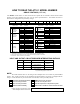
HOW TO READ THE AT10.1 MODEL NUMBER GROUP I RATINGS (6-25 Adc) Your AT10.1 model number is coded to describe the options that are included. Please find the model number on the data nameplate and write it in the spaces provided below. Then follow the chart to determine the configuration of your battery charger. AT10 A A B C DESCRIPTION CODE FEATURE SERIES AT10 AT10.
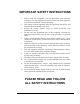
IMPORTANT SAFETY INSTRUCTIONS 1. Before using this equipment, read all instructions and cautionary markings on: A) this equipment, B) battery, and C) any other equipment to be used in conjunction with this equipment. 2. This manual contains important safety and operating instructions, and therefore should be filed for easy access. 3. Remove all jewelry, watches, rings, etc. before proceeding with installation or service. 4.
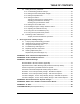
TABLE OF CONTENTS QUICK OPERATION .................................................................................................. Back Cover HOW TO READ THE AT10.1 MODEL NUMBER ..........................................Inside Front Cover IMPORTANT SAFETY INSTRUCTIONS ......................................................................................i 1 Receiving and Installing the AT10.1 Battery Charger 1.1 Storing the AT10.1 ...........................................................................
TABLE OF CONTENTS 2.3 Setting the AT10.1 parameters 2.3.1 Understanding parameter settings .................................................................30 2.3.2 Setting the Float and Equalize voltages.........................................................31 2.3.3 Setting the Equalize timer ..............................................................................32 2.3.4 Setting the Alarms..........................................................................................
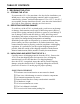
TABLE OF CONTENTS 1. RECEIVING THE AT10.1 1.1. STORING THE AT10.1 If you store the AT10.1 for more than a few days before installation, you should store it in its original shipping container, and in a temperature controlled, dry climate. Ambient temperatures of 32 to 122° F / 0 to 50° C are acceptable. Storage should not exceed 2 years due to the limited shelf life of the dc filter capacitors when they are not in service. 1.2. REPORTING SHIPPING DAMAGE If, on delivery of the AT10.
RECEIVING THE AT10.1 1.4. MOVING THE AT10.1 Once you have established that the AT10.1 is undamaged, identify the enclosure style and weight of your unit. Refer to the table below. AT10.
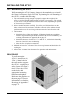
INSTALLING THE AT10.1 1.5.1. Wall-Mounting the AT10.1 Wall-mounting the AT10.1 battery charger is the standard way to install the Group I enclosures (Style-586/594). In planning for wall mounting of the AT10.1 consider the following: 1. The wall must be strong enough to properly support the weight of the AT10.1. See the Weight Table located in section 1.4 on page 3. The weight of your AT10.1 may be different from the table value, depending on options or accessories you ordered. 2.
INSTALLING THE AT10.1 WALL-MOUNTING THE AT10.
INSTALLING THE AT10.1 1.5.2. Floor-Mounting the AT10.1 To floor mount the AT10.1, you must use the floor mounting accessory kit (part number EI0192-00). For kit availability, see ordering information in Appendix B on page 71. The kit contains brackets that elevate the top of the AT10.1 approximately 47in / 1194mm above floor level, with provision for floor anchoring. The kit includes an instruction sheet (JA0083) showing assembly dimensions and mounting details.
INSTALLING THE AT10.1 FLOOR-MOUNTING THE AT10.1 - GRAPHICS ENCLOSURE Style-586 Style-594 A DIMENSION (in / mm) B C D 16.50 / 419 46.63 / 1184 11.75 / 298 15.00 / 381 19.75 / 502 47.75 / 1213 14.25 / 361 18.
INSTALLING THE AT10.1 1.5.3. Rack-Mounting the AT10.1 The AT10.1 can be installed in most relay racks with standard EIA hole spacing (see the table below for the allowable combinations). The rack mounting kit (part number EI0193-00), includes mounting brackets and the necessary hardware to install one AT10.1 battery charger. The kit includes an instruction sheet (JA0091) showing installation details. For kit availability see ordering information in Appendix B on page 71. When rack mounting the AT10.
INSTALLING THE AT10.1 RACK-MOUNTING THE AT10.1 - GRAPHICS Style-586 Enclosure Style-594 Enclosure NOTES: 1. Units are installed from the front. 2. Units shown above without penthouse enclosure. If penthouse is used, add 7in / 178mm to top of enclosure. 3. Refer to the outline drawings in Appedix C for enclosure dimensions.
INSTALLING THE AT10.1 1.6. CHANGING TRANSFORMER TAPS Before you wire ac power to the AT10.1, check the wiring of the main transformer T1, to be sure it is connected for your ac input voltage. The AT10.1 accepts standard input voltages of 120, 208 or 240 Vac by changing jumpers on T1. No other changes are required. The AT10.1 is wired at the factory for 240 Vac, except on special order. Models for 220, 380 or 416 Vac at 50/60 Hz are available on special order. EXCEPTION: An AT10.
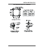
INSTALLING THE AT10.1 CHANGING TRANSFORMER TAPS - GRAPHICS 480 V PRIMARY T1 CONNECTION TABLE INPUT VAC JUMPERS 120/208/240 V PRIMARY H4 H5 SECONDARY X1 H5 120 H1-H3, H2-H5 H2 208 H2-H4 (2) JUMPERS H3 240 H2-H3 (2) JUMPERS 480 NONE X4 H1 Y2 H1 Y1 TRANSFORMER SCHEMATIC PROCEDURE: 1) BE SURE ALL VOLTAGES ARE DE-ENERGIZED AND LOCKED OUT. 2) BE SURE TERMINALS ARE FULLY SEATED (586 ENCL). . 3) BE SURE STUD TERMINALS ARE TIGHT (594 ENCL). 4) CHECK YOUR WORK AFTER COMPLETION.
INSTALLING THE AT10.1 1.7. MAKING THE AC INPUT CONNECTIONS Follow these steps to connect ac power to the AT10.1: 1. Use a branch circuit breaker or fused disconnect switch, properly sized for the maximum input current of the AT10.1, as shown in the table below. This device should have lockout capability so that the ac input can be deenergized and locked out for maintenance. A time delay circuit breaker or slow-blow fuse is recommended. 2.
INSTALLING THE AT10.1 MAKING THE AC INPUT CONNECTIONS - GRAPHICS NOTES: 1. The drawing above does not show other components mounted to the I/O panel. Be careful not to disconect any other component leads. 2. Always use a proper ground. 3. On 120 Vac input, connect the neutral leg to the terminal L2. 4. Wire insulation must be rated for 194° F / 90° C or better. 5. Use copper or aluminum conductors only.
INSTALLING THE AT10.1 1.8. MAKING THE DC OUTPUT CONNECTIONS Follow these steps to connect the battery to the AT10.1: 1. Size the dc wiring to minimize voltage drop. The acceptable wire size depends on your installation. As a guideline, the voltage drop should not exceed 1% of nominal output voltage at full current. Refer to the table below to determine the voltage drops for various wire sizes, currents and distances. WIRE SIZING CHART VOLTAGE DROP PER 100ft / 30.
INSTALLING THE AT10.1 MAKING THE DC OUTPUT CONNECTIONS - GRAPHICS NOTES: 1. The drawing above does not show other components mounted to the I/O panel. Be careful not to disconect any other component leads. 2. Always use a proper ground. 3. Wire insulation must be rated for 194° F / 90° C or better. 4. Use copper or aluminum conductors only.
INSTALLING THE AT10.1 1.9. WIRING THE AT10.1 FOR REMOTE SENSING You can wire the AT10.1 to regulate the output voltage at the battery terminals, instead of at the charger output terminals. Remote sensing does the following: 1. Compensates for voltage drop in the dc wiring between the AT10.1 and the battery. 2. Directly monitors the battery or dc bus voltage. The front panel meter displays the actual voltage on the dc bus. You wire the AT10.1 for remote sensing by installing a two-wire cable from the AT10.
INSTALLING THE AT10.1 PROCEDURE 1. De-energize and lock out all ac and dc voltages within the AT10.1 enclosure. Check with a voltmeter. 2. Remove safety shield. 3. Wire the AT10.1 remote sense to the dc bus as shown in the figure below. 4. Move wires # 72 and # 74 from the TB1 (-) and (+) dc output terminals to the corresponding remote sense terminals as shown in the lower left figure. 5.
INSTALLING THE AT10.1 1.10. WIRING TO THE REMOTE ALARM CONTACTS Built-in common alarm relay The Primary Alarm functions are included as standard equipment with the AT10.1. The Common Alarm relay, located on the main control circuit board on the back of the door, provides one form C summary alarm (common alarm) contact that transfers for any alarm. Follow the procedure below to wire a remote annunciator to this contact. See section 2.2.7 for a description of the alarm functions. PROCEDURE 1.
INSTALLING THE AT10.
INSTALLING THE AT10.1 1.11. INSTALLING TEMP. COMPENSATION ASSEMBLY (OPTIONAL) The temperature compensation assembly consists of a probe containing a temperature-dependent resistor in an epoxy module that you install near your battery. There are three steps in installing the assembly: 1. Mounting the probe assembly near the battery. 2. Installing an interconnection cable from the probe assembly to the AT10.1. 3. Wiring the charger end of the cable to a terminal block on the main control circuit board.
INSTALLING THE AT10.1 • • Run the cable though a conduit if possible, but not through a conduit containing any power wiring. Route the other end to the probe at the battery and coil up excess cable. NOTE: If the standard (25ft / 7.6m) cable isn't long enough, longer cable assemblies are available in lengths of 50, 100 & 200ft / 15.2, 30.5 & 61.0m. See Appendix B on page 71 for ordering information. • Be sure your wiring conforms to the NEC and your facility requirements. 5.
INSTALLING THE AT10.1 7. Check your work. Be sure that: • All connections are secure. • The shield is connected to ground at the charger end only (on the main circuit board). • The cable is connected to TB8 on the circuit board. Other terminal blocks may look similar. 8. Restart the AT10.1 using the startup procedure in section 2.1. During startup, the AT10.1 displays LEAD on the front panel, indicating that the temperature compensation is set up for lead-acid batteries.
INSTALLING THE AT10.1 Please note the following: • • • • • You should set the Float and Equalize voltages to the values recommended by your battery manufacturer for 77° F (25° C). When you enter the Edit mode to adjust the Float or Equalize voltage (see section 2.3.2), the front panel meter shows the 77° F (25° C) value for the Float or Equalize voltage, even if the battery is warmer or cooler than 77° F (25° C). The actual output voltage of the AT10.
OPERATING THE AT10.1 2. OPERATING THE AT10.1 BATTERY CHARGER 2.1. STARTING THE AT10.1 2.1.1. Understanding the startup sequence The AT10.1 is set up at the factory to work with most common batteries and loads without further adjustment. When you start the AT10.1 for the first time, the factory settings (float voltage, equalize voltage, etc.) control the operation of the charger. You can change the settings after you start the charger. The FACTORY SETTINGS are shown in table on page 25. The AT10.
OPERATING THE AT10.1 • • • If you have an optional temperature compensation probe installed, the front panel displays LEAD during startup, indicating that the temperature compensation is set up for lead-acid batteries. While this is being displayed, you can press any front panel key to change the display to read NICD, to change the temperature compensation setup for nickel cadmium batteries. The choice you make is saved internally, and will be used again by the AT10.1 then next time it starts.
OPERATING THE AT10.1 2.2. USING THE AT10.1 FRONT PANEL FEATURES 2.2.1. If the meter displays an error message When you apply power to the AT10.1 for the first time, the microprocessor control circuit performs a diagnostic check of the system. If it finds anything wrong, it writes an error code to the display, such as E 01. Below is a list of the error codes. See section 3.2 for a full explanation of each error code. Error Code Explanation E 01 Resistor R2 is open or defective.
OPERATING THE AT10.1 2.2.3. Selecting the Float or Equalize mode The AT10.1 has 2 output voltage settings, Float and Equalize. Use the Float mode for all normal battery charging and to operate your dc system. Use the Equalize mode if it is necessary to balance the level of charge among the cells of the battery. Consult your battery data sheets for information on equalize-charging your battery. • Press the CHRG MODE key to change to the equalize mode.
OPERATING THE AT10.1 Manual Equalize Method Choose the manual equalize method when you want to equalize charge the battery, but only when you are able to monitor the battery voltage and gassing rate. After you select the manual equalize method, press the CHRG MODE key to put the charger into the equalize mode. The EQLZ indicator will light. Press the CHRG MODE key again to return the charger to the float mode. The FLOAT indicator will light. NOTE: Never leave the AT10.
OPERATING THE AT10.1 2.2.5. Testing the front panel indicators • Press the DOWN key. This is also the LAMP TEST key. The meter will display 8888, and all status & alarm indicators will light. The LAMP TEST key does not test the AC ON indicator. The AC ON indicator lights whenever ac power is present, and the ac circuit breaker is turned on. The LAMP TEST key does not operate when ac power is off. To test the action of the summary alarm relay, press and hold the LAMP TEST key for four seconds.
OPERATING THE AT10.1 2.3. SETTING PARAMETERS IN THE AT10.1 2.3.1. Understanding Parameter Settings You can change the settings of the AT10.1 while the charger is operating, using the front panel controls. The changes you make take effect immediately, and are saved internally. If the charger is taken out of service, and then later returned to service, it restarts using the last values you set.
OPERATING THE AT10.1 2.3.2. Setting the Float and Equalize voltages • Press the EDIT/ENTER key. The FLOAT and DC VOLTS indicators light, and the display flashes the present value of the float voltage. Press and release the UP or DOWN key to increase or decrease the value in the display by one count, or press and hold the UP or DOWN key to scroll the value in the display upward or downward. When the display shows the float voltage you want to set, release the UP or DOWN key.
OPERATING THE AT10.1 2.3.3. Setting the Equalize Timer • Press the EDIT/ENTER key until the EQLZ HRS REMAINING, MANUAL TIMER and AUTO EQLZ TIMER indicators light, and the display flashes the present value of the equalize timer duration in hours. Press and release the UP or DOWN key to increase or decrease the value in the display by one count, or press and hold the UP or DOWN key to scroll the value in the display upward or downward.
OPERATING THE AT10.1 Setting the High DC Voltage Alarm • Press the EDIT/ENTER key until the HIGH DC VOLTAGE indicator flashes, and the display flashes the present value of the high dc voltage alarm. Press and release the UP or DOWN key to increase or decrease the value in the display by one count, or press and hold the UP or DOWN key to scroll the value in the display upward or downward. When the display shows the high dc voltage alarm point that you want to set, release the UP or DOWN key.
OPERATING THE AT10.1 Adjusting Ground Detection Sensitivity You can adjust the sensitivity of the ground detection alarm circuit. You must have a test resistor whose value is the sensitivity you want. You can adjust the sensitivity from 5 to 50 kΩ. The potentiometer for adjusting ground detection circuit sensitivity is located on the main control circuit board. It is the lower of the two potentiometers labeled RA3 SENS, as shown in the figure at the right.
OPERATING THE AT10.1 Disabling the Ground Detection Alarm You can disable the ground detection alarm circuit, and isolate the circuit from chassis ground. If your battery is normally grounded, or you want to defeat the alarm for any other reason, follow these steps: • • De-energize and lock out all ac and dc voltage sources to the AT10.1. Check with a voltmeter before proceeding. This includes remote sense wires if they were installed. Open the AT10.
OPERATING THE AT10.1 2.3.6. Enabling the High DC Voltage shutdown feature The AT10.1 has a built-in high dc voltage shutdown feature. In case of any maladjustment or internal failure that results in a continuous output voltage that is too high, the AT10.1 shuts down after 30 seconds to protect the battery. The digital display reads E 03, and the summary alarm relay contact transfers. The AT10.1 is shipped with the high dc voltage shutdown feature disabled.
OPERATING THE AT10.1 2.3.7. Adjusting the Voltmeter Accuracy The AT10.1 voltmeter is adjusted at the factory to display the actual output voltage within ±1%. If you replace any component that affects meter accuracy, such as the main control PC board or R4, you should readjust the meter. This adjustment procedure is different from all others, because the meter reading remains constant, while the output voltage of the charger changes.
OPERATING THE AT10.1 2.3.8. Using the Low Level Detector (LLD) The AT10.1 charger is equipped with a summary alarm safety override circuit. This safety feature forces the summary alarm (common alarm) relay contact to transfer, sending an alarm, even if there is a catastrophic failure of the control circuitry. A low battery voltage triggers the safety circuit. If you have a dc power supply, you can adjust the battery voltage that triggers the alarm.
OPERATING THE AT10.1 2.3.9. Using the front panel security feature The AT10.1 charger is shipped with all the front panel keys enabled. You can disable these front panel functions: • Selecting Equalize method • Changing settings using the EDIT/ENTER key • Toggling the high dc voltage shutdown feature Open the front panel, and locate the small plastic jumper J9 on the right side of the main control board. See the figure below. Move the jumper to the DISABLE position.
OPERATING THE AT10.1 2.4. Performing routine maintenance WARNING: High voltages appear at several points inside the battery charger. Use extreme caution when working inside the charger. Do not attempt to work inside the charger unless you are a qualified technician or electrician. Disconnect and lock out all power to the battery charger before starting any maintenance procedures. Turn the ac power off at the distribution panel upstream from the battery charger.
OPERATING THE AT10.1 2.4.4. Check temperature compensation probe (optional) If you are using the optional temperature compensation probe, be sure that the probe is securely installed. Be sure the connectors and the wiring from the probe to the AT10.1 charger are in good condition. If there is a failure of the temperature compensation probe, or the wiring, the AT10.1 charger displays the error code E 08. 2.4.5. Measuring the output ripple voltage (filtered models only) If your AT10.
OPERATING THE AT10.1 SAMPLE PREVENTIVE MAINTENANCE PROCEDURE AT10.1 BATTERY CHARGER Suggested frequency: every 6 months Maintenance date Step Instructions (standard features) Clean battery charger • • Check all electrical connections and wiring • • • Check ac input voltage • Check dc output voltage • Check ripple voltage Test font panel indicators Test common alarm relay 42 Performed by • • • All vents clean and open. Remove dust and debris from inside of unit. TB1 connections all tight.
OPERATING THE AT10.1 Exercise front panel controls • • • • • Check voltage and alarm settings • Final checks • • • Step Instructions (optional features) Test auxiliary alarm relays Check integrity of remote sense or temperature compensation wiring Switch from float to equalize, then back to o OK float. Turn off the dc circuit breaker. E 07 o OK should appear on display (requires at least 5% of rated output current). Reset breaker. Cycle through meter modes.
SERVICING THE AT10.1 3. SERVICING THE AT10.1 3.1. A STEP-BY-STEP TROUBLESHOOTING PROCEDURE The AT10.1 battery charger is fully tested and calibrated at the factory and should work for years with a minimum of attention. If you do encounter trouble, there are three steps you should take to find the problem and return the charger to service. 1. Check the front panel meter for an error code. The AT10.1 is able to diagnose common problems with the battery charger, or with the application or installation.
SERVICING THE AT10.1 3.2. INTERPRETING FRONT PANEL ERROR MESSAGES If the AT10.1 control circuit detects a hardware or wiring problem, it may display an error code on the front panel. To solve the problem, use the table starting below, which lists the error codes and the procedures to use. WARNING: High voltages appear at several points inside the battery charger. Use extreme caution when working inside the charger.
SERVICING THE AT10.1 Error Code E 04 Meaning Repair Procedure Internal memory Any parameters that you set, such as Float or Equalize voltage, are failure saved internally. The internal memory is tested on startup. If the memory test fails, E 04 appears on the front panel display. The error may also appear if the controller was trying to write to the memory while a power failure occured. If an E 04 appears, try restarting the AT10.1 by turning the ac and dc breakers off, then on.
SERVICING THE AT10.1 Error Code E 08 Meaning Repair Procedure Defective temperature compensation probe If a temperature compensation probe is connected to the AT10.1, the control circuit detects the probe on startup, and uses the temperature measured by the probe to control the output voltage of the charger. To understand temperature compensation, see section 1.11. If the temperature compensation probe, or the wiring that connects it to the AT10.1, fails during normal operation, the AT10.
SERVICING THE AT10.1 3.3. USING THE TROUBLESHOOTING CHART WARNING: High voltages appear at several points inside the battery charger. Use extreme caution when working inside the charger. Do not attempt to work inside the charger unless you are a qualified technician or electrician. Disconnect and lock out all power from the battery charger before starting to remove or replace any components. Turn the ac power off at the distribution panel upstream from the battery charger.
SERVICING THE AT10.1 3.4. TROUBLESHOOTING CHART SYMPTOM PROBABLE CAUSE AC breaker trips immediately 1. Shorted rectifier diode or SCR RECOMMENDED ACTION 1. Test by disconnecting wire # 12 from the rectifier assembly. Measure resistance between the two top rectifier terminals (labeled "AC" on the wiring diagram); it should be at least 100,000 Ohms (check both polarities). Replace rectifier assembly if resistance is low in either direction. 2.
SERVICING THE AT10.1 SYMPTOM DC breaker trips after a few minutes No output current, but ac and dc breakers are on; AC ON lamp is out PROBABLE CAUSE 1. Loose connection to breaker 2. Open SCR RECOMMENDED ACTION 1. Check and tighten connections as required. 2. Use a clamp-on ammeter to measure the current in wire # 12 or # 11. If it less than 70% of the dc output current, then one of the SCRs or diodes is defective. Replace the rectifier module. 3.
SERVICING THE AT10.1 SYMPTOM No output current, but ac and dc breakers are on; AC ON lamp is on PROBABLE CAUSE 1. Battery is fully charged 2. Float or Equalize voltage set too low 3. Wrong ac input voltage, or T1 taps miswired 4. Defective wiring RECOMMENDED ACTION 1. This is normal operation in a system with little or no dc load. As long as the charger maintains Float voltage, it is operating normally. 2. Check the Float and Equalize voltages and adjust them if necessary.
SERVICING THE AT10.1 SYMPTOM PROBABLE CAUSE RECOMMENDED ACTION 1. Use a dc voltmeter to measure the dc voltage from E17 on the I/O panel to TB1(-). It is normally 12 Vdc when the rated output voltage is at TB1(+) and TB1(-). Remove all power from the charger, and measure the resistance from TB1(+) and E17. See the table in section 3.6 for the proper resistance values. If the resistance is not within 10% of the table value, replace R3. 2. Remove the enclosure shroud, and check the wiring to and 2.
SERVICING THE AT10.1 SYMPTOM PROBABLE CAUSE 1. Current limit Charger set too low never reaches float (or equalize) voltage (within 1%) 2. Defective battery or dc load, or load is too great 3. Wrong ac input voltage, or voltage too low, or T1 wired incorrectly 4. Defecive rectifier bridge 5. Defective control circuit board A1 Input current too high 1. Wrong ac input voltage, or transformer T1 wired incorrectly 2. Defective rectifier bridge RECOMMENDED ACTION 1. If the AT10.
SERVICING THE AT10.1 SYMPTOM PROBABLE CAUSE Charger very 1. Loose noisy hardware or enclosure panel 2. Defective rectifier bridge RECOMMENDED ACTION 1. Remove the enclosure shroud. Check and tighten all component mounting hardware. Replace the shroud, being sure all assembly hardware is secure. 2. Use a clamp-on ammeter to measure the ac current in wire # 11 or # 12 (connected between T1 and the rectifier assembly). If it less than 70% of the dc output current, one of the SCRs or diodes is defective.
SERVICING THE AT10.1 SYMPTOM PROBABLE CAUSE HIGH DC 1. High DC VOLTAGE Voltage alarm indicator is on and Equalize voltage settings are mismatched 2. Defective rectifier bridge 3. Defective control circuit board A1 RECOMMENDED ACTION 1. Be sure that the High DC Voltage alarm setting is higher than the Equalize voltage setting. See sections 2.3.2 and 2.3.4. 2. Disconnect wire # 24 from terminal E3 of the rectifier assembly (near the left front of the enclosure). Restart the charger.
SERVICING THE AT10.1 SYMPTOM PROBABLE CAUSE DC OUTPUT FAILURE 1. Defective rectifier bridge RECOMMENDED ACTION 1. Use a clamp-on ammeter to measure the current in wire # 12 or # 11. If it is less than 70% of the dc output current, one indicator is of the SCRs or diodes is defective. Replace the rectifier on, but ac module. and dc 2. Defective 2. Turn off both front panel circuit breakers. Then turn on the breakers are control circuit dc breaker, followed by the ac breaker.
SERVICING THE AT10.1 SYMPTOM PROBABLE CAUSE POS GND or NEG GND 1. Ground fault on external dc indicator is on bus 2. Ground detection circuit needs calibration 3. Defective wiring 4. Defective control circuit board A1 Summary 1. Defective alarm relay is control circuit in alarm board A1 mode, but no front panel alarm indicator is on RECOMMENDED ACTION 1. Disconnect the charger from the battery and dc bus, and check the battery and dc bus for a ground fault. 2.
SERVICING THE AT10.1 3.5. REPLACING DEFECTIVE COMPONENTS WARNING: High voltages appear at several points inside the battery charger. Use extreme caution when working inside the charger. Do not attempt to work inside the charger unless you are a qualified technician or electrician. Disconnect and lock out all power from the battery charger before starting to remove or replace any components. Turn the ac power off at the distribution panel upstream from the battery charger.
SERVICING THE AT10.1 Replacing the control circuit board (A1) CAUTION: A1 is sensitive to damage from static discharges. Leave the circuit board in its anti-static bag until you are ready to install it. Ground yourself before handling the board by touching the ground stud on the back of the door. Handle the board only by the edges. Turn off all power to the charger. Disconnect the battery from the output terminals. If the optional temperature compensation probe is installed, disconnect the leads from TB8.
SERVICING THE AT10.1 Rotate the rectifier assembly into position in the enclosure. Line up the metal tab with the mounting hole on the back wall of the charger and slide the assembly into position. Replace the shroud as described in the previous section. Tighten all screws and restart the AT10.1. Replacing the optional dc filter assembly (A7) The dc filter assembly consists of a diode heat sink, inductor L2, and one or two capacitors installed on a single bracket. Turn off all power to the charger.
SERVICING THE AT10.1 Replacing the main transformer (T1) Deenergize and lock out all ac and dc voltage sources to the AT10.1. Check with a voltmeter before proceeding. This includes remote sense wires if they were installed. Remove the enclosure shroud and the safety shield. Disconnect the harness wires # 28 and # 29 from the upper row of transformer terminals. Disconnect wires # 11 and # 12 from the top of the rectifier heat sink.
SERVICING THE AT10.1 Replacing the dc surge suppressor (VR1) Turn off all power to the charger. Disconnect the battery from the output terminals. Remove the safety shield. Remove the hardware from the output terminal TB1(+), and remove the lead of the dc surge suppressor. Install one lead of the replacement surge suppressor. Replace the other wires and the hardware. Repeat for the output terminal TB1(-). Tighten all hardware. NOTE: The surge suppressor is not polarized.
SERVICING THE AT10.1 Replacing the scaling resistor (R4) Locate the scaling resistor R4 on TB5 on the back of the front panel, just above the control circuit board. The resistor (R4 is the one on the left) is mounted on two quick-connect terminals. Remove the resistor by grasping the terminals by the plastic insulation, and pulling out and downward. Install the replacement resistor by pushing the terminals firmly onto the quick-connect blades on the terminal block.
SERVICING THE AT10.1 3.6. ORDERING REPLACEMENT PARTS To order replacement parts, please provide the following information for each component: • • • • Circuit symbol from the schematic diagram (see Appendix) Factory part number and description, from the table below Model number and serial number of your battery charger Quantity required Call your sales representative to place an order for spare parts or replacement parts.
SERVICING THE AT10.1 Factory Part Number Symbol Description 12 Vdc 24 Vdc 48 Vdc Rec.
SERVICING THE AT10.
SERVICING THE AT10.
SERVICING THE AT10.1 Table 3-10: RATING RESISTOR (R2) Current Rating 6A 12A 16A 20A 25A 12 Vdc 24 Vdc 48 Vdc 130 Vdc EJ1133-00 34.8 KΩ EJ1133-01 40.2 KΩ EJ1133-02 53.6 KΩ EJ1133-03 78.7 KΩ EJ1133-04 118 KΩ EJ1133-05 13.0 KΩ EJ1133-06 15.4 KΩ EJ1133-07 19.6 KΩ EJ1133-08 23.7 KΩ EJ1133-09 29.4 KΩ EJ1133-10 5.11 KΩ EJ1133-11 6.19 KΩ EJ1133-12 7.50 KΩ EJ1133-13 9.09 KΩ EJ1133-14 11.0 KΩ EJ1133-15 1.50 KΩ EJ1133-16 2.21 KΩ EJ1133-17 2.74 KΩ EJ1133-18 3.57 KΩ EJ1133-19 4.
SERVICING THE AT10.
APPENDIX A SPECIFICATIONS All specifications apply at 77° F / 25 °C, 120 Vac, nominal Float voltage except as noted Specification Output voltage regulation Conditions 12 Vdc Vac +10%, -12% 0 to 100% load 24 Vdc 48 Vdc 130 Vdc ± 0.25% Temp. 32-122° F / 0-50° C Freq. 60 ± 3 Hz Transient response Efficiency 20-100% load change, with battery connected Output voltage change ± 4% maximum Recovery to ± 2.0% in 200 ms Recovery to ± 0.5% in 500 ms 12 Adc rating, full load, % 67.00 72.00 78.00 85.
APPENDIX B FIELD INSTALLABLE ACCESSORIES AND OPTIONS All accessories/options listed below are available in kits for field installation. Kits contain all parts and hardware with detailed installation instructions. To order accessories/options, please provide the following information for each kit: • Factory part number and description, from the table below • Model number and serial number of your battery charger • Quantity required Contact your sales representative to place an order for accessories/options.
APPENDIX C (Standard Drawings) Outline - AT10.1 Group I Battery Charger: NEMA-1 Style-586 (JE5023-03) Note: Online standard drawings, saved in Adobe Acrobat Portable Document Format (PDF), for the AT10.1 Series Battery Charger are available for downloading and printing. Please contact your sales representative for document availability or see the manufacturer's web site listed on the back cover of this manual.
APPENDIX C (Standard Drawings) Outline - AT10.1 Group I Battery Charger: NEMA-1 Style-594 (JE5024-03) Note: Online standard drawings, saved in Adobe Acrobat Portable Document Format (PDF), for the AT10.1 Series Battery Charger are available for downloading and printing. Please contact your sales representative for document availability or see the manufacturer's web site listed on the back cover of this manual.
APPENDIX C (Standard Drawings) AT10.1 Optional Enclosure Outline Drawings Stlye-586 with Penthouse and Drip Shield DIMENSION in mm WW DD H 16.25 12.50 15.63 495 324 457 W D 16.25 10.75 495 337 WW DD H 14.00 10.75 22.63 356 337 572 W D 16.25 10.00 495 324 WW DD H 18.75 12.50 19.50 559 318 552 W D 16.25 10.75 495 337 WW DD H 18.75 12.50 26.50 476 337 729 W D 16.25 10.
APPENDIX C (Standard Drawings) AT10.1 Optional Enclosure Outline Drawings Stlye-594 with Penthouse and Drip Shield DIMENSION in mm WW DD H 19.50 12.75 18.00 495 324 457 W D 19.50 13.25 495 337 WW DD H 14.00 13.25 25.00 356 337 635 W D 19.50 12.75 495 324 WW DD H 22.00 12.50 21.75 559 318 552 W D 19.50 13.25 495 337 WW DD H 18.75 13.25 28.75 476 337 729 W D 19.50 12.
APPENDIX C (Standard Drawings) Internal Component Layout Detail - AT10.1 Group I Battery Charger w/Common Options (JE5027-99) Note: Online standard drawings, saved in Adobe Acrobat Portable Document Format (PDF), for the AT10.1 Series Battery Charger are available for downloading and printing. Please contact your sales representative for document availability or see the manufacturer's web site listed on the back cover of this manual.
APPENDIX C (Standard Drawings) Internal Component Layout Detail - AT10.1 Group I Battery Charger w/Common Options (JE5027-99) Note: This particular internal component layout drawing (JE5027-99) depicts an AT10.1 Group I battery charger with ALL available options. Standard components (A1 through VR7) are featured in all Group I units. Optional components (A5 through VR3) are featured only on those AT10.1 battery chargers configured with such options.
APPENDIX C (Standard Drawings) Instrument Panel Detail - AT10.1 Group I Battery Charger w/Optional Auxiliary Relay PC Board (JE5030-19) Note: Online standard drawings, saved in Adobe Acrobat Portable Document Format (PDF), for the AT10.1 Series Battery Charger are available for downloading and printing. Please contact your sales representative for document availability or see the manufacturer's web site listed on the back cover of this manual.
APPENDIX C (Standard Drawings) Instrument Panel Detail - AT10.1 Group I Battery Charger w/Optional Auxiliary Relay PC Board (JE5030-19) Note: This instrument panel drawing (JE5030-19) depicts the optional Auxiliary Alarm Relay PC Board (A5), which provides two (2) sets of individual form-c contacts (TB4) for all alarm conditions. Standard AT10.1 battery chargers feature one (1) set of form-c summary (common) alarm contacts (TB3).
APPENDIX C (Standard Drawings) Schematic - AT10.1 Group I Battery Charger Standard w/o Options (JE5031-00) Note: Online standard drawings, saved in Adobe Acrobat Portable Document Format (PDF), for the AT10.1 Series Battery Charger are available for downloading and printing. Please contact your sales representative for document availability or see the manufacturer's web site listed on the back cover of this manual.
APPENDIX C (Standard Drawings) Schematic - AT10.
APPENDIX C (Standard Drawings) Schematic - AT10.1 Group I Battery Charger with Common Options (JE5031-99) Note: Online standard drawings, saved in Adobe Acrobat Portable Document Format (PDF), for the AT10.1 Series Battery Charger are available for downloading and printing. Please contact your sales representative for document availability or see the manufacturer's web site listed on the back cover of this manual.
APPENDIX C (Standard Drawings) Schematic - AT10.
APPENDIX C (Standard Drawings) Connection Diagram - AT10.1 Group I Battery Charger Standard w/o Options (JE5033-00) Note: Online standard drawings, saved in Adobe Acrobat Portable Document Format (PDF), for the AT10.1 Series Battery Charger are available for downloading and printing. Please contact your sales representative for document availability or see the manufacturer's web site listed on the back cover of this manual.
APPENDIX C (Standard Drawings) Connection Diagram - AT10.
APPENDIX C (Standard Drawings) Connection Diagram - AT10.1 Group I Battery Charger with Common Options (JE5033-99) Note: Online standard drawings, saved in Adobe Acrobat Portable Document Format (PDF), for the AT10.1 Series Battery Charger are available for downloading and printing. Please contact your sales representative for document availability or see the manufacturer's web site listed on the back cover of this manual.
APPENDIX C (Standard Drawings) Connection Diagram - AT10.
APPENDIX D RECOMMENDED FLOAT AND EQUALIZE VOLTAGES This table contains suggested values for commonly used batteries. Consult your battery manufacturer's documentation for specific values and settings for your battery type. Lead-Acid Types Battery Cell Type Antimony 1.215 Sp. Gr. Antimony 1.250 Sp. Gr. Calcium 1.215 Sp. Gr. Calcium 1.250 Sp. Gr. Absorbed / Gelled Electrolyte * (sealed Lead-Acid type) Nickel Cadmium Recommended Float Voltage/cell Recommended Equalize Voltage/cell 2.17 2.20 2.25 2.29 2.
APPENDIX E / F COMMUNICATIONS MODULE Your AT10.1 Battery Charger has provisions for an optional Communications Module that allows the user to remotely monitor and control the charger over a serial connection. This PC Board Assembly (A12) supports DNP3 Level 2 and Modbus protocols over RS-232 or RS-485 half-duplex. The system can be used with a modem for telephone communications. All features of the AT10.1’s front instrument panel are accessible remotely, using this option.
CUSTOMER NOTES MANUAL REVISION: The text and graphics contained within this manual are controlled by the battery charger manufacturer's internal part number (JA5023-00). The revision level of this manual's text and graphics are featured in the electronic filename listed below. The revision dates are also listed below and supercede all other available dates. The first two and last two pages of this manual are reserved for company-specific front and back cover artwork.
QUICK OPERATION For unpacking and installation instructions, see section 1 on page 2 in this manual To learn how to use the equalize timers, see sections 2.2.4 on page 27 and 2.3.3 on page 32 Startup „ Turn on the dc breaker, labeled “DC OUTPUT”. „ Turn on the ac breaker, labeled “AC INPUT”. Changing between Float and Equalize Modes „ Press the key to toggle from Float mode to Equalize mode. Press again to toggle back to Float. The green or yellow indicator identifies the current mode.