Cisco UCS B200 M3 Blade Server Installation and Service Note Cisco UCS B200 M3 Blade Server 2 LEDs 2 Buttons 4 Connectors 4 Hard Drive Replacement 4 Blade Server Removal and Installation 6 Secure Digital (SD) Card Access 9 Removing a Blade Server Cover 9 Working Inside the Blade Server 13 Enabling a Trusted Platform Module 30 Server Troubleshooting 31 Server Configuration 31 Physical Specifications for the Cisco UCS B200 M3 31 Related Documentation 31 Obtaining Documentation and Submitting a Service Request
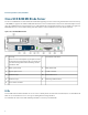
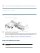
Revised: September 9, 2013, OL-26624-01 Cisco UCS B200 M3 Blade Server The Cisco UCS B200 M3 is an Intel-based, half-width blade supporting two CPU sockets using Intel E5-2600 series CPUs and up to 24 DIMMs; it supports one modular LOM (dedicated slot for Cisco's Virtual Interface Card) and one mezzanine adapter. At this time, the UCS B200 M2 (second generation) server is still available and is documented elsewhere.
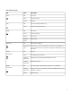
Table 1: Blade Server LEDs LED Color Description Power Off Power off. Green Normal operation. Amber Standby. Off None of the network links are up. Green At least one network link is up. Off Power off. Green Normal operation. Amber Minor error. Blinking Amber Critical error. Off Beaconing not enabled. Link Health Beaconing Blinking blue Beaconing to locate a selected blade—If the LED is not blinking, the 1 Hz blade is not selected.
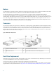
Buttons The Reset button is just inside the chassis and must be pressed using the tip of a paper clip or a similar item. Hold the button down for five seconds, and then release it to restart the server if other methods of restarting are not working. The beaconing function for an individual server may get turned on or off by pressing the combination button and LED.
Before upgrading or adding an HDD to a running system, check the service profile in Cisco UCS Manager and make sure the new hardware configuration will be within the parameters allowed by the service profile. To prevent ESD damage, wear grounding wrist straps during these procedures and handle modules by the carrier edges only. Caution RAID Considerations Each blade contains an LSI SAS 2004 RAID controller embedded in the motherboard that is not separately replaceable.
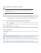
Step 2 Step 3 Place the hard drive on an antistatic mat or antistatic foam if you are not immediately reinstalling it in another server. Install a hard disk drive blank faceplate (N20-BBLKD) to keep dust out of the blade server if the slot will remain empty. Installing a Blade Server Hard Drive Procedure Step 1 Place the hard drive lever into the open position by pushing the release button.
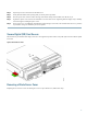
Powering Off Blade Servers Using the Power Button Tip You can also shut the server down remotely using Cisco UCS Manager. For details, see the Configuration Guide for the version of Cisco UCS Manager that you are using. The configuration guides are available at the following URL: http://www.cisco.com/en/US/products/ps10281/products_installation_and_ configuration_guides_list.html Procedure Step 1 For each server in the chassis that you want to power off, check the color of the Power Status LED.
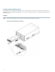
Installing a Half-width Blade Server UCS B200 M3 and UCS B22 M3 half-width blade servers are interoperable in a UCS chassis with any other UCS blade servers, including prior generation B200 M2 and B200 M1 servers, or other UCS B-Series blade servers. To install a half-width blade server, follow these steps: Procedure Step 1 Grasp the front of the blade server and place your other hand under the blade to support it.
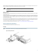
Step 2 Step 3 Step 4 Step 5 Step 6 Open the ejector lever in the front of the blade server. Gently slide the blade into the opening until you cannot push it any farther. Press the ejector lever so that it catches the edge of the chassis and presses the blade server all the way in. Tighten the captive screw on the front of the blade to no more than 3 in-lbs. Tightening with bare fingers only is unlikely to lead to stripped or damaged captive screws. Power on the server.
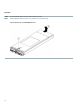
Procedure Step 1 Step 2 Press and hold the button down as shown in the figure below. While holding the back end of the cover, pull the cover back and then up.
Air Baffles The air baffles direct and improve air flow for the server components. Two identical baffles ship with each B200 M3 server. No tools are necessary to install them, just place them over the DIMMs as shown, with the holes in the center of the baffles aligned with the corresponding motherboard standoffs.
Internal Components Figure 9: Inside View of the B200 M3 Blade Server 1 Hard drive bays 2 Internal USB connector Cisco UCS-USBFLSH-S-4GB= is recommended, but if another USB drive will be used it must be no wider than .8 inches, and no more than 1.345 inches long in order tp provide needed clearances to install or remove the USB drive.
populating DIMMs in a blade server, and the rules depend on the blade server model. Refer to the documentation for a specific blade server for those rules. HDD status LEDs are on the front face of the HDD. Faults on the CPU, DIMMs, or adapter cards also cause the server health LED to light solid amber for minor error conditions or blinking amber for critical error conditions.
d) Replace the server in the chassis and power on the blade by pressing the Power button. Figure 10: Location of the Motherboard CMOS Battery CPU and Heatsink Replacement Special Information For Upgrades to Intel E5-2600 v2 Series CPUs Caution You must upgrade your server firmware to the required minimum level before you upgrade to Intel E5-2600 v2 Series CPUs. Older firmware versions cannot recognize the new CPUs and this results in a non-bootable server.
Server CIMC 2.1(3) Server BIOS 2.1(3) Cisco UCS Manager 2.1(3) Board controller firmware 8.0 Do one of the following actions: • If your server’s firmware and/or Cisco UCS Manager software are already at the required levels shown in the table above, you can replace the CPU hardware by using the procedures in this section.
Step 3 Unhook the first socket hook, which has the following icon: Step 4 Unhook the second socket hook, which has the following icon: Open the socket latch. See callout 5 in the following figure. Step 5 See callout 3 in the following figure. See callout 4 in the following figure. Figure 11: Removing the Heat Sink and Accessing the CPU Socket Step 6 Press the central button on the provided CPU pick and place tool (UCS-CPU-EP-PNP=) to release the catch.
c) Lift the tool and CPU straight up. Figure 12: Proper Alignment of CPU Pick and Place Tool (for Intel Xeon E5-2600 Series Processors) 1 Alignment mark on the button/handle of the pick and place tool 2 Alignment mark on the socket Installing a New CPU and Heat Sink Before installing a new CPU in a server, verify the following: • The CPU is supported for that given server model.
Procedure Step 1 (Optional) If you are installing a CPU in a socket that had been shipped empty, there will be a protective cap intended to prevent bent or touched contact pins. The pick and pull cap tool provided can be used in a manner similar to a pair of tweezers. Grasp the protective cap and pivot as shown. Figure 13: Protective Cap Removal Step 2 Step 3 18 Release the catch on the pick and place tool by pressing the handle/button.
e) Lift the tool and CPU straight up off of the pedestal.
Step 4 Step 5 Place the CPU and tool on the CPU socket with the registration marks aligned as shown. Press the button/handle on the pick and place tool to release the CPU into the socket.
Step 6 Step 7 Close the socket latch. See callout 1 in the following figure. Step 8 Secure the second hook, which has the following icon: Secure the first hook, which has the following icon: See callout 2 in the following figure. See callout 3 in the following figure.
Figure 17: Thermal Grease Application Pattern Step 10 Step 11 Replace the heat sink. See callout 4. Caution On certain models, heat sinks are keyed to fit into the plastic baffle extending from the motherboard. Do not force a heat sink if it is not fitting well, rotate it and re-orient the heat sink. Secure the heat sink to the motherboard by tightening the four captive screws a quarter turn at a time in an X pattern as shown in the upper right.
Procedure Step 1 Open both DIMM connector latches. Figure 18: Installing DIMMs in the Blade Server Step 2 Press the DIMM into its slot evenly on both ends until it clicks into place. DIMMs are keyed, if a gentle force is not sufficient, make sure the notch on the DIMM is correctly aligned. Be sure that the notch in the DIMM aligns with the slot. If the notch is misaligned you may damage the DIMM, the slot, or both. Press the DIMM connector latches inward slightly to seat them fully.
Memory Arrangement The blade server contains 24 DIMM slots—12 for each CPU. Each set of 12 DIMM slots is arranged into four channels, where each channel has three DIMMs. Figure 19: Memory Slots within the Blade Server 1 Channels A-D for CPU 1 2 Channels E-H for CPU 2 DIMMs and Channels Each channel is identified by a letter—A, B, C, D for CPU1, and E, F, G, H for CPU 2. Each DIMM slot is numbered 0, 1, or 2.
The figure below shows how DIMMs and channels are physically laid out on the blade server. The DIMM slots in the upper and lower right are associated with the second CPU (CPU shown on right in the diagram), while the DIMM slots in the upper and lower left are associated with the first CPU (CPU shown on left).
The figure below shows a logical view of the DIMMs and channels. Figure 21: Logical Representation of DIMMs and Channels DIMMs can be used in the blade server in a one DIMM per Channel (1DPC) configuration, in a two DIMMs per Channel (2DPC) configuration, or a three DIMMs per Channel (3DPC) configuration. Each CPU in a Cisco UCS B200 M3 blade server supports four channels of three memory slots each. In a 1 DPC configuration, DIMMs are in slot 0 only.
Table 3: Supported DIMM Population Order DIMMs per CPU CPU 1 installed slots CPU 2 installed slots 1 A0 E0 2 A0, B0 E0, F0 3 A0, B0, C0 E0, F0, G0 4 (Blue slots) A0, B0, C0, D0 E0, F0, G0, H0 5 A0, B0, C0, D0, A1 E0, F0, G0, H0, E1 6 A0, B0, C0, D0, A1, B1 E0, F0, G0, H0, E1, F1 7 A0, B0, C0, D0, A1, B1, C1 E0, F0, G0, H0, E1, F1, G1 8 (Blue and black slots) A0, B0, C0, D0, A1, B1, C1, D1 E0, F0, G0, H0, E1, F1, G1, H1 9 A0, B0, C0, D0, A1, B1, C1, D1,A2 E0, F0, G0, H0, E1, F1,
Installing a Modular LOM The Cisco VIC 1240 is a specialized modular Lan on Motherboard (mLOM) adapter that provides dual 2 x 10 Gb of Ethernet/ or Fiber Channel over Ethernet (FCoE) connectivity to each chassis. It plugs into the dedicated mLOM connector only. It is currently the only card that can be plugged into the mLOM connector and it will provide connectivity through either a 2100 series or 2200 series IOM. Note You must remove the adapter card to service the modular LOM.
Installing an Adapter Card The network adapters and interface cards all have a shared installation process and are constantly being updated. A list of currently supported and available models for this server is in the specification sheets at this URL: http://www.cisco.com/en/US/products/ps10280/products_data_sheets_list.html Note If a VIC 1240 mLOM is not installed, you must have an adapter card installed.
Tip Removing an adapter card is the reverse of installing it. You might find it helpful when removing the connector from the motherboard to gently rock the board along the length of the connector until it loosens. Figure 23: Installing an Adapter Card Enabling a Trusted Platform Module The Trusted Platform Module (TPM, Cisco Product ID UCSX-TPM1-001) is a component that can securely store artifacts used to authenticate the server. These artifacts can include passwords, certificates, or encryption keys.
Procedure Step 1 Step 3 Step 4 Enable Quiet Mode in the BIOS policy of the server’s Service Profile. Establish a direct connection to the server, either by connecting a keyboard, monitor, and mouse to the front panel using a KVM dongle (N20-BKVM) or by other means. Reboot the server. Press F2 during reboot to enter the BIOS setup screens. Step 5 On the Advanced tab, select Trusted Computing and press Enter. Step 6 Set the TPM Support option to Enable. Step 7 Press F10 to save and exit.
http://www.cisco.com/go/unifiedcomputing/b-series-doc For specifics on which component models are supported on which servers refer to the server's Technical Specifications ordering guide at: http://www.cisco.com/en/US/products/ps10493/products_data_sheets_list.
THE SPECIFICATIONS AND INFORMATION REGARDING THE PRODUCTS IN THIS MANUAL ARE SUBJECT TO CHANGE WITHOUT NOTICE. ALL STATEMENTS, INFORMATION, AND RECOMMENDATIONS IN THIS MANUAL ARE BELIEVED TO BE ACCURATE BUT ARE PRESENTED WITHOUT WARRANTY OF ANY KIND, EXPRESS OR IMPLIED. USERS MUST TAKE FULL RESPONSIBILITY FOR THEIR APPLICATION OF ANY PRODUCTS.
Americas Headquarters Cisco Systems, Inc. San Jose, CA 95134-1706 USA Asia Pacific Headquarters Cisco Systems (USA) Pte. Ltd. Singapore Europe Headquarters Cisco Systems International BV Amsterdam, The Netherlands Cisco has more than 200 offices worldwide. Addresses, phone numbers, and fax numbers are listed on the Cisco Website at www.cisco.com/go/offices.