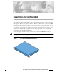
Installation and Configuration This document is written assuming that you have already determined the 802.11 topology as described in the Appliance Mode sections in the Product Guide. Because the Radio Resource Management (RRM) feature automatically detects and configures the access points as they appear on the network, it is not necessary to have any access points on the network to install and configure controllers. The controller is a slim 9 x 5.5 x 1.5 in. (22.9 x 14.0 x 3.
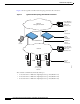
Installation and Configuration Figure 2 shows a typical controller network topology and network connections: Figure 2 Typical Controller Topology and Network Connections Optional management network 10/100BASE-T Cisco Wireless control System, Web User Interface, CLI Service port connections Serial console connection Two 1000BASE-SX CLI console Network Distribution system connections Cisco wireless control system, Web User Interface, CLI Cisco 1000 access points network 142200 Access point connect
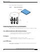
Installation and Configuration Collecting Required Tools and Information Figure 3 shows a typical controller deployment. Figure 3 Typical Controller Deployment Cisco Wireless LAN Controller Network 142197 Cisco 1000 Access Points Collecting Required Tools and Information This section lists the tools and the information that you need to have before installing the controller.
Installation and Configuration Collecting Required Tools and Information Note The Cisco WCS uses an integral TFTP server. This means that third-party TFTP servers cannot run on the same workstation as the Cisco WCS, because the Cisco WCS and the third-party TFTP servers use the same communication port. Initial System Configuration Information Obtain the following initial configuration parameters from the wireless LAN/network planner: Note • System (Controller) name.
Installation and Configuration Determining a Physical Location • 802.11a network enabled or disabled? • 802.11g network enabled or disabled? • Radio Resource Management (RRM) (Auto-RF) enabled or disabled? Determining a Physical Location The controller can be installed almost anywhere, but it is more secure and reliable if installed in a secure equipment room or wiring closet.
Installation and Configuration Determining a Physical Location Varning! Aviso Advarsel Laserprodukt av klass 1. Produto a laser de classe 1. Klasse 1 laserprodukt. • Ensure that the power cord can reach a 110 or 220 VAC grounded electrical outlet.
Installation and Configuration Installing the Chassis Installing the Chassis This section describes how to install the controller chassis. Warning Only trained and qualified personnel should be allowed to install, replace, or service this equipment. Statement 1030 Waarschuwing Varoitus Deze apparatuur mag alleen worden geïnstalleerd, vervangen of hersteld door bevoegd geschoold personeel. Tämän laitteen saa asentaa, vaihtaa tai huoltaa ainoastaan koulutettu ja laitteen tunteva henkilökunta.
Installation and Configuration Installing the Chassis Aviso Advarsel Somente uma equipe treinada e qualificada tem permissão para instalar, substituir ou dar manutenção a este equipamento. Kun uddannede personer må installere, udskifte komponenter i eller servicere dette udstyr. The controller is shipped with rack-mounting ears attached, and rubber feet to mount in a separate bag. Install the controller as follows: • Note You can remove the rack mounting ears from the controller, if desired.
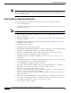
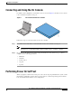
Installation and Configuration Connecting and Using the CLI Console Connecting and Using the CLI Console For initial system configuration, use the CLI console. As shown in Figure 4, the CLI console connects to the controller front-panel console port. CLI Console Connection to a controller 142201 Figure 4 Follow these steps to connect the CLI console to the controller: Step 1 Use a null-modem serial cable to connect the CLI console to the controller console port.
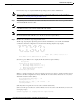
Installation and Configuration Performing Power On Self Test Perform these steps to complete POST and Operating System software initialization: Note Step 1 This procedure is written assuming that you have connected the CLI console to the controller as described in “Connecting and Using the CLI Console.” Plug an AC power cord into the rear of the controller, and connect the other end to a grounded 100 to 240 VAC 50/60 Hz electrical outlet.
Installation and Configuration Using the Startup Wizard OS Version 3.0.80.0 Checking for new bootloader: Upgrading...
Installation and Configuration Logging In Logging In To log into the controller, perform these steps: Step 1 Enter a valid login and password to enter the CLI. User: Password: Note Step 2 The login and password functions are case sensitive. The default administrative user login and password are admin and admin, respectively. The CLI displays the root-level system prompt: (system prompt)> The system prompt can be any alphanumeric string up to 31 characters.
Installation and Configuration Connecting the Service Port Interfaces Figure 5 External Equipment Connections to the Controller Optional management network 10/100BASE-T Cisco Wireless control System, Web User Interface, CLI Service port connections Serial console connection Two 1000BASE-SX CLI console Network Distribution system connections Cisco wireless control system, Web User Interface, CLI 142200 Access point connections Cisco 1000 access points network Connecting the Service Port Interface
Installation and Configuration Connecting the Service Port Interfaces • For a front-panel Cisco Wireless Control System, Web User Interface, or CLI console connection, use CAT-5, CAT-5e, CAT-6, or CAT-7 ethernet cables to connect the Cisco Wireless Control System (Cisco WCS) Server, Web User Interface, or another CLI console to the dedicated front-panel Service port.
Installation and Configuration Connecting Access Points Connecting Access Points After you have installed and configured the controller, use CAT-5, CAT-5e, CAT-6, or CAT-7 ethernet cables to connect the access points to the network (Distribution System) as shown in the following figure. Note As soon as the controller is activated, it starts to scan for access points on all connected ports. When it detects an access point, it records its MAC address in its database.
Installation and Configuration Where to Go from Here Cisco 4100 Series Wireless LAN Controllers - Installation and Configuration Guide 16 78-17155-01