Cisco Video Surveillance IP Camera User Guide Model CIVS-IPC-2500 Americas Headquarters Cisco Systems, Inc. 170 West Tasman Drive San Jose, CA 95134-1706 USA http://www.cisco.
NOTICE. ALL STATEMENTS, INFORMATION, AND RECOMMENDATIONS IN THIS MANUAL ARE BELIEVED TO BE ACCURATE BUT ARE PRESENTED WITHOUT WARRANTY OF ANY KIND, EXPRESS OR IMPLIED. USERS MUST TAKE FULL RESPONSIBILITY FOR THEIR APPLICATION OF ANY PRODUCTS. THE SOFTWARE LICENSE AND LIMITED WARRANTY FOR THE ACCOMPANYING PRODUCT ARE SET FORTH IN THE INFORMATION PACKET THAT SHIPPED WITH THE PRODUCT AND ARE INCORPORATED HEREIN BY THIS REFERENCE.
C O N T E N T S Preface v Overview v Organization v Obtaining Documentation, Obtaining Support, and Security Guidelines CHAPTER 1 Overview 1-1 IP Camera Features 1-1 IP Camera Physical Details 1-2 DC Auto Iris Lens Connector Pinouts Package Contents CHAPTER 2 Getting Started 1-6 1-6 2-1 Installing the IP Camera 2-1 Performing the Initial Setup of the IP Camera Accessing the IP Camera Windows Powering the IP Camera On or Off Resetting the IP Camera 3 2-7 2-7 2-8 Configuring and M
Contents Video Window Audio Window 3-14 3-17 Security Windows 3-18 Product Process Window 3-19 Initialization Window 3-19 Complexity Window 3-20 Applications Windows 3-20 Mail & FTP Window 3-21 Motion Detection Window 3-23 Event Window 3-24 SNMP Window 3-26 Alarm I/O Ports Window 3-27 PTZ (RS-485) Window 3-28 Preset Positions Window 3-30 Status Windows 3-31 System Window 3-32 Audio/Video Window 3-32 Network Window 3-33 Syslog & Log Window 3-34 Video Log Window 3-37 CHAPTER Viewing and Live Video 4 4-
Preface Overview This document, Cisco Video Surveillance IP Camera User Guide provides information about installing, configuring, using, managing, and troubleshooting the Cisco Video Surveillance IP Camera model CIVS-IPC-2500.
Preface Obtaining Documentation, Obtaining Support, and Security Guidelines Subscribe to the What’s New in Cisco Product Documentation as a Really Simple Syndication (RSS) feed and set content to be delivered directly to your desktop using a reader application. The RSS feeds are a free service and Cisco currently supports RSS version 2.0.
CH A P T E R 1 Overview This chapter provides an overview of the Cisco Video Surveillance IP Camera and its features. It includes these topics: Note • IP Camera Features, page 1-1 • IP Camera Physical Details, page 1-2 • DC Auto Iris Lens Connector Pinouts, page 1-6 • Package Contents, page 1-6 If you use the IP camera with Cisco Video Surveillance Manager (VSM), not all IP camera features are currently supported. These features are noted throughout this manual.
Chapter 1 Overview IP Camera Physical Details • Motion detection—The IP camera can detect motion in up to three designated fields of view by analyzing changes in pixels and generate an alert if motion is detected. • Flexible scheduling—You can configure the IP camera to respond to events that occur within a designated schedule. • Syslog support—The IP camera can send log data to a Syslog server.
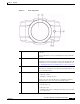
Chapter 1 Overview IP Camera Physical Details Figure 1-1 1 Front of IP Camera Lens opening The IP camera supports a variety of C and CS mount lenses, which attach here. For best performance, Cisco recommends that you use a DC auto iris lens. 2 Focus ring Allows you to adjust the back focus of the IP camera. You must loosen the focus ring hex screw on the bottom of the IP camera before you can rotate the focus ring.
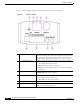
Chapter 1 Overview IP Camera Physical Details Figure 1-2 and the table that follows describe the items on the rear of the IP camera. Figure 1-2 Rear of IP Camera 1 Reset button Recessed button that reboots the IP camera or resets it to a default state. You can use a pin or paper clip to depress it. It can be used any time that the IP camera is on and can have various effects, as described in the “Resetting the IP Camera” section on page 2-8.
Chapter 1 Overview IP Camera Physical Details 7 Microphone input Allows the connection of an optional external microphone (with pre-amplifier) through a standard 3.5 mm mini phone jack. Microphones that are designed for use with PCs usually are compatible with this input jack. Connecting an external microphone disables the internal microphone on the IP camera.
Chapter 1 Overview DC Auto Iris Lens Connector Pinouts DC Auto Iris Lens Connector Pinouts Figure 1-4 and the table that follows describe the pinouts of the DC auto iris lens connector on the IP camera.
CH A P T E R 2 Getting Started This chapter provides instructions for installing and performing the initial setup of the Cisco Video Surveillance IP Camera. It also describes how to access the IP camera through a web browser so that you can configure it or view video from it, and how to perform other important tasks.
Chapter 2 Getting Started Installing the IP Camera Warning The power supply must be placed indoors. Statement 331 Note If you use the IP camera outdoors, place the camera and the power supply in a suitable NEMA enclosure. Warning This product requires short-circuit (overcurrent) protection, to be provided as part of the building installation. Install only in accordance with national and local wiring regulations.
Chapter 2 Getting Started Installing the IP Camera Table 2-1 Step 4 Installing the IP Camera (continued) Action Explanation Optional. Connect a microphone to the microphone input jack on the rear of the IP camera. Connecting an external microphone disables the IP camera internal microphone. Place the external microphone in a location that allows it to capture the audio that you want. The microphone must include a pre-amplifier. Step 5 Optional.
Chapter 2 Getting Started Performing the Initial Setup of the IP Camera Table 2-1 Installing the IP Camera (continued) Action Step 10 Check the LEDs on the IP camera. Explanation • The Ready LED blinks while the IP camera starts up. After 15 to 20 seconds, startup completes and the Ready LED should remain on. • Step 11 Mount the IP camera in the desired location. The Network LED should be on.
Chapter 2 Getting Started Accessing the IP Camera Windows Step 2 In the Set Password and Verify Password fields in the Admin column, enter a password for the IP camera administrator. You must enter the same password in both fields. The password is case sensitive and must contain at least eight characters, which can be letters, numbers, and special characters, but no spaces. Special characters are: ! " # $ % & ' ( ) * + , - . : ; < = > ? @ [ \ ] ^ _ ` { | } ~.
Chapter 2 Getting Started Accessing the IP Camera Windows You need this information to access the IP camera windows: • IP address of the IP camera. The default IP address is 192.168.0.100. • Port number, if other than the default value. Default port numbers for the IP camera are 443 for HTTPS and 80 for HTTP. The IP camera administrator can enable an alternative HTTPS port and an alternative HTTP port as described in the “Advanced Setup Window” section on page 3-7.
Chapter 2 Getting Started Adjusting Back Focus on the IP Camera The Main window appears and video from the IP camera starts playing automatically. You can take these actions in the Main window: • Click the Setup link to access configuration menus for the camera. For detailed information about these menus, see Chapter 3, “Configuring and Managing the IP Camera.” • Click the Home link to view and control live video from the camera.
Chapter 2 Getting Started Resetting the IP Camera • If the IP camera is receiving power through the power adapter, unplug the adapter from the wall or disconnect it from the camera Resetting the IP Camera You reset the IP camera by pressing the Reset button on the rear of the device (see ). There are various reset types, as described in Table 2-2. You also can perform some reset operations from the Maintenance window as described in the “Maintenance Window” section on page 3-12.
CH A P T E R 3 Configuring and Managing the IP Camera The Cisco Video Surveillance IP Camera provides configuration windows that you use to configure and manage the IP camera. This chapter explains how to access the configuration windows, describes each window, and provides detailed information about the options that are available in each window.
Chapter 3 Configuring and Managing the IP Camera Configuration Overview Configuration Overview There are many settings and options that you can configure for the IP camera. The items that you configure depend on several factors, including your camera model, operational requirements, and connected external devices. Table 3-1 provides general information to help you determine what items you need to configure for your situation.
Chapter 3 Configuring and Managing the IP Camera Configuration Overview Table 3-1 Guidelines for Configuring the IP Camera (continued) Configuration Item Explanation Guidelines for Use Audio options Includes options for audio Required if you use the internal See the “Audio Window” section streams that are received or sent or an external microphone, or an on page 3-17. by the IP camera. external speaker. Security options Optional.
Chapter 3 Configuring and Managing the IP Camera Navigating the Configuration Windows Navigating the Configuration Windows After you access the configuration windows as described in the “Accessing the IP Camera Windows” section on page 2-5, a window appears that includes the following components: • Navigation tree—Appears at the left of the window and provides links to each configuration window • Basic Setup window—Appears at the right of the window The navigation tree always appears.
Chapter 3 Configuring and Managing the IP Camera Setup Windows • Status – System – Audio Video – Network – Syslog & Log – Video Log Setup Windows The Setup windows let you configure a variety of basic and advanced settings for the IP camera, and to designate IP addresses that are allowed or denied access to the IP camera. The following sections describe the Setup windows in detail: • Basic Setup Window, page 3-5. • Advanced Setup Window, page 3-7. • IP Filter Window, page 3-9.
Chapter 3 Configuring and Managing the IP Camera Setup Windows Table 3-2 Basic Setup Window Options (continued) Option Description Enable LED Operations Check this check box if you want the Ready LED or Activity LED on the front of the IP camera to light when the IP camera receives power or performs an activity. If you do not check this check box, these LEDs do not light. Current Date/Time Display only. Current date and time of the internal clock of the IP camera.
Chapter 3 Configuring and Managing the IP Camera Setup Windows Table 3-2 Basic Setup Window Options (continued) Option Description Subnet Mask If you configured the IP camera for a fixed IP address, enter the subnet mask for the IP camera. Use the same value that is configured for the PCs on your network. Gateway If you configured the IP camera for a fixed IP address, enter the gateway for the IP camera. Use the same value that is configured for the PCs on your network. Primary DNS Optional.
Chapter 3 Configuring and Managing the IP Camera Setup Windows Table 3-3 Advanced Setup Window Options (continued) Option Description Enable HTTPS Alternative Port Check this check box to enable Internet access to the IP camera through an HTTPS port other than the default port 443. If you enable this option, enter a port number from 1024 through 65535.
Chapter 3 Configuring and Managing the IP Camera Setup Windows Table 3-3 Advanced Setup Window Options (continued) Option Description Audio Address Appears if you enabled multicast. Enter the multicast IP address on which the IP camera sends an audio stream. The default value is 224.2.0.1. Audio Port Appears if you enabled multicast. Enter the port on which the IP camera sends a multicast audio stream. Valid values are even numbers 1024 through 65534. The default value is 2242.
Chapter 3 Configuring and Managing the IP Camera Administration Windows Table 3-4 IP Filter Window Options Option Description Options Choose the option that specifies how to control IP addresses from which the IP camera can be accessed: Single/Range • Disable—Do not use the IP address filtering feature. In this case, the IP camera can be accessed from a device with any IP address.
Chapter 3 Configuring and Managing the IP Camera Administration Windows • To remove a user, click Delete next to the user. If you delete a user who is logged into the IP camera, the user remains logged in and can continue access the IP camera. • To discard the changes before you click Change or Save, click Cancel. • The Save and Cancel buttons appear at the bottom of the window. You may need to scroll down to see them. Table 3-5 describes the options in the Users window.
Chapter 3 Configuring and Managing the IP Camera Administration Windows Maintenance Window The Maintenance window provides options for resetting or restarting the IP camera, saving configuration information from the IP camera, and uploading the configuration information to the IP camera.
Chapter 3 Configuring and Managing the IP Camera Administration Windows Table 3-6 Maintenance Window Options (continued) Option Description Upload Path and folder where a configuration file is stored. You can click Browse to find this location. After you enter this information, click Upload and follow the on-screen prompts load the configuration file to the IP camera. After you upload a configuration file to the IP camera, the IP camera restarts automatically.
Chapter 3 Configuring and Managing the IP Camera Audio/Video Windows Audio/Video Windows The Audio/Video windows provide options for configuring audio and video from the IP camera. The following sections describe the Setup windows in detail: • Video Window, page 3-14. • Audio Window, page 3-17 Video Window The Video window provides options for configuring the video from the IP camera. You can configure settings for the primary and an optional secondary video stream.
Chapter 3 Configuring and Managing the IP Camera Audio/Video Windows Table 3-8 Video Window Options (continued) Option Description Max. Frame Rate Select the desired maximum frame rate for the primary video stream from the IP camera. The default values are 30 for NTSC and 25 for PAL.
Chapter 3 Configuring and Managing the IP Camera Audio/Video Windows Table 3-8 Video Window Options (continued) Option Description Preset Choose one the following preset white balance modes from the Preset drop-down list: • Normal—Suitable for most conditions that do not have special lighting • Indoor—Suitable for indoor conditions when the Normal setting does not provide a clear image • Fluorescent—Suitable for indoor conditions with fluorescent lighting • Outdoor—Suitable for outdoor condit
Chapter 3 Configuring and Managing the IP Camera Audio/Video Windows Table 3-8 Video Window Options (continued) Option Description Day/Night Vision Switch Mode Choose the day/night mode for the IP camera: • Auto—IP camera automatically switches between day and night mode based on lighting thresholds that you specify. • Day—IP camera always remains in day mode. In this mode, the camera displays video images in color. • Night—IP camera always remains in Night mode.
Chapter 3 Configuring and Managing the IP Camera Security Windows Table 3-9 Audio Window Options Option Description Enable Audio Check this check box to enable audio from the IP camera, and choose one of these options: Enable Microphone • Simplex - Listen Only—Enables a simplex connection that allows you to receive audio from the IP camera but not transmit audio to the IP camera • Simplex - Talk Only—Enables a simplex connection that allows you to transmit audio to the IP camera but not receive
Chapter 3 Configuring and Managing the IP Camera Security Windows Product Process Window The Product Process window displays the processes that occupy TCP or UDP ports, and lets you stop any of these processes. Take care when stopping processes because some processes are required for the camera to operate properly. Processes that you stop in this window can restart the next time that you log in to the IP camera.
Chapter 3 Configuring and Managing the IP Camera Applications Windows Table 3-11 Initialization Window Options (continued) Option Description HTTP Click the Enable radio button if you want to allow both HTTP and HTTPS connections to the IP camera. By default, the IP camera allows only HTTPS connections. SSH Click the Enable radio button is you want to allow access to the camera through a SSH connection.
Chapter 3 Configuring and Managing the IP Camera Applications Windows Mail & FTP Window When the IP camera detects an event, it can send an e-mail message to up to three designated recipients. The e-mail notifies recipients that an event occurred and provides access to video of the event. The Mail & FTP window includes options for configuring how such messages are sent. You enable e-mail alerts and configure options for event video files as described in the “Event Window” section on page 3-24.
Chapter 3 Configuring and Managing the IP Camera Applications Windows Table 3-13 Mail & FTP Window Options (continued) Option Description SMTP Mail Server Enter the name or IP address of the primary SMTP server. If you enter a name, you must configure the Primary DNS option as described in the “Basic Setup Window” section on page 3-5. Authentication If the primary SMTP server requires authentication to send e-mail, choose the appropriate authentication type.
Chapter 3 Configuring and Managing the IP Camera Applications Windows Table 3-13 Mail & FTP Window Options (continued) Option Description Port Enter the port number of the primary FTP server to which event video files are uploaded. The default value is 21. Login name Enter the log in name of the primary FTP Server. Password Enter the password of the primary FTP Server. File Path Name Enter path where the event video file is stored on the primary FTP server.
Chapter 3 Configuring and Managing the IP Camera Applications Windows Table 3-14 Motion Detection Window Options Option Description Full Screen Check this check box to cause the IP camera to examine its entire video field for activity. If you check this check box, you can use these options: Setting Custom Area • Indicator—Display only. Horizontal bar that represents how much activity is being detected in the area.
Chapter 3 Configuring and Managing the IP Camera Applications Windows If you change any options in the Event window, except deleting an event from the event schedule list, you must click Save to save the changes. To discard the changes, click Cancel before clicking Save. These buttons appear at the bottom of the window. You may need to scroll down to see them. Table 3-15 describes the options in the Event window. Note These features are not currently supported if you use the IP camera with Cisco VSM.
Chapter 3 Configuring and Managing the IP Camera Applications Windows Table 3-15 Event Window Options (continued) Option Description Actions Choose the desired options to designate actions that the camera takes when events occur: • E-Mail—Causes an e-mail message to be delivered to the SMTP server. The e-mail alerts users that an event has occurred, and may include a video file of the event and the URL of an FTP server from which users can download the video file.
Chapter 3 Configuring and Managing the IP Camera Applications Windows To display the SNMP window, access the configuration windows as described in the “Performing the Initial Setup of the IP Camera” section on page 2-4, click Applications, then click SNMP. If you change any options in the SNMP window, you must click Save to save the changes. To discard the changes, click Cancel before clicking Save. These buttons appear at the bottom of the window. You may need to scroll down to see them.
Chapter 3 Configuring and Managing the IP Camera Applications Windows Table 3-17 Alarm I/O Ports Window Options Option Description Alarm Input Settings Current Status Display only. For each input port on the IP camera, displays its current state (high or low). Trigger Events When For each input port on the IP camera, Input 1 and Input 2, choose the state (high or low) that triggers designated camera actions.
Chapter 3 Configuring and Managing the IP Camera Applications Windows If you change any options in the PTZ (RS-485) window, you must click Save to save the changes. To discard the changes, click Cancel before clicking Save. These buttons appear at the bottom of the window. You may need to scroll down to see them. Table 3-18 describes the options in the PTZ (RS-485) window. Note These features are not currently supported if you use the IP camera with Cisco VSM.
Chapter 3 Configuring and Managing the IP Camera Applications Windows Table 3-18 PTZ (RS-485) Window Options (continued) Option Description Patrol Sequence Patrol Sequence Configure the order in which the IP camera executes preset operations. The preset list contains up to 9 positions that you configure as described in the “Preset Positions Window” section on page 3-30. The Sequence list specifies the order in which the IP camera goes to each preset position when you execute a sequence.
Chapter 3 Configuring and Managing the IP Camera Status Windows Table 3-19 Preset Positions Options (continued) Option Description Navigation Keys Set the pan and tilt positions as follows: Focus Far button • To pan the IP camera, use the left or right arrow buttons • To tilt the IP camera, use the up or down arrow buttons • To move the IP camera to its home position, click the Move Camera Home button, which is located in the middle of the group of arrow keys Use these buttons to control focu
Chapter 3 Configuring and Managing the IP Camera Status Windows System Window The System window displays information about the IP camera. To display the System window, access the configuration windows as described in the “Performing the Initial Setup of the IP Camera” section on page 2-4, click Status, then click System. To make sure that the System window shows the most current information, click the Refresh button. Table 3-20 describes the options in the System window. All options are for display only.
Chapter 3 Configuring and Managing the IP Camera Status Windows Table 3-21 describes the options in the Audio/Video window. All options are for display only. Note This window is not currently supported if you use the IP camera with Cisco VSM. Table 3-21 Audio/Video Window Options Option Description MPEG-4 Settings 1 Resolution Image size of the primary video stream. Image Quality Image quality of the primary video stream. Frame Rate Frame rate of the primary video stream.
Chapter 3 Configuring and Managing the IP Camera Status Windows Syslog & Log Window The Syslog & Log window lets you manage the IP camera log file, which captures and stores information about the IP camera and its activities. The IP camera captures the information that you specify and stores the log file in its internal SDRAM. If the SDRAM becomes full, the IP camera begins to overwrite existing information.
Chapter 3 Configuring and Managing the IP Camera Status Windows Table 3-23 Syslog & Log Window Options (continued) Option Description Log List Log List pane Displays information from the log type or types that you specified. For an explanation of each log message that can appear, see Table 3-24. Refresh Click the Refresh button to update the information in the Log List pane. Clear Log Click the Clear Log button to delete all messages in the log file.
Chapter 3 Configuring and Managing the IP Camera Status Windows Table 3-24 Syslog and Log Information (continued) Message Explanation LOG: Clear all messages. You have used the Clear Log button to delete the log file from the IP camera SDRAM. LOG: Log file is full. Start to wrap around. The IP camera SDRAM is full and existing log information is beginning to be overwritten. Network: Failed to get the IP address. Camera set IP camera is unable to obtain an IP address to default IP address.
Chapter 3 Configuring and Managing the IP Camera Status Windows Table 3-24 Syslog and Log Information (continued) Message Explanation System: Invalid upgrade file You are attempting to upgrade firmware for the IP camera but are using and invalid firmware file. System: Reset to factory defaults. Factory reset procedure performed for the IP camera. Web: Invalid login attempt. [id: User_ID, ip: Address] Provides information when someone logs in, or attempts to log in, to the IP camera.
Chapter 3 Configuring and Managing the IP Camera Status Windows The IP camera stores video log files in its internal SDRAM. When the SDRAM becomes full, the IP camera stops storing additional video files or begins overwriting the oldest video files, depending on the setting of the Overwrite/Replace oldest video file when SDRAM is full option in the Event window. (See the “Event Window” section on page 3-24 for additional information.
CH A P T E R 4 Viewing and Live Video After you install and set up the Cisco Video Surveillance IP Camera as described in Chapter 2, “Getting Started,” users can connect to the IP camera through Internet Explorer and access the Home window to view live video from the IP camera. The home window also provides for controlling the video display and certain IP camera functions. Available controls depend on the user type or privilege level.
Chapter 4 Viewing and Live Video Viewing Video through the Home Window Overview Figure 4-1 Home Window 1 Digital zoom factor. For information about digital zooming, see the “Home Window Controls” section on page 4-3. 2 IP camera date and time. You configure the date and time for the IP camera as described in the “Basic Setup Window” section on page 3-5. 3 Video display and audio controls. For detailed information, see the “Home Window Controls” section on page 4-3.
Chapter 4 Viewing and Live Video Viewing Video through the Home Window Overview Home Window Controls The Home window provides controls for several IP camera features. Table 4-1 describes the controls in the Home window. Note The IP camera administrator and users with the administrator or monitor privilege can access all IP camera, video display, and audio controls. Users with the viewer privilege can access video display and audio controls only.
Chapter 4 Viewing and Live Video Viewing Video through the Home Window Overview Table 4-1 Home Window Controls (continued) Control Description IP camera control buttons To pan the IP camera, use the left or right arrow buttons. To tilt the IP camera, use the up or down arrow buttons. To move the IP camera to its home position, click the Move Camera Home button, which is located in the middle of the group of arrow keys.
Chapter 4 Viewing and Live Video Viewing Video through the Home Window Overview Table 4-1 Home Window Controls (continued) Control Description Snapshot button Captures and saves a snapshot image of the current video image in the format and location of your choice, and with the file name of your choice. When you click this button, follow these steps to save the image: Speaker Off toggle button 1. In the Snapshot window, click Save. 2.
Chapter 4 Viewing and Live Video Viewing Video through Third-Party Devices or Software Viewing Video through Third-Party Devices or Software You can allow users to access video streams from the IP camera through third-party mobile devices, or through the VLC media player or equivalent software. To do so, you must configure the RTSP Port option in the Advanced Setup window. This option enables the IP camera to receive Real-Time Streaming Protocol (RTSP) commands.
Chapter 4 Viewing and Live Video Viewing Video through Third-Party Devices or Software Accessing the Secondary Stream by using Devices or Software other than VLC Player In the following command, replace ip_address with the IP address of the IP camera, and replace code with the Access Code that you configured for the secondary stream in the Video window. After you enter the command, enter your IP camera user name and password when prompted.
Chapter 4 Viewing and Live Video Viewing Video through Third-Party Devices or Software Cisco Video Surveillance System IP Camera User Guide 4-8 OL-14220-01
CH A P T E R 5 Troubleshooting This chapter describes some common problems that may be encountered while using the IP camera and provides possible solutions. Symptom Cannot connect to an IP camera through a web browser.
Chapter 5 Troubleshooting Symptom The motion detection feature does not send e-mail alerts. Possible Cause The e-mail alert feature is not properly configured or the SMTP server that the IP camera uses to send the e-mail may be filtering e-mail to prevent spam from being sent from your server. Recommended Action Configure e-mail alerts as described in the “Basic Setup Window” section on page 3-5, the “Mail & FTP Window” section on page 3-21, and the “Event Window” section on page 3-24.
A P P E N D I X A Using the IP Camera with Cisco VSM Cisco Video Surveillance Manager (VSM) is a suite of powerful and flexible video surveillance applications that interoperate with a wide range of devices and cameras to provide a complete, standards-based video surveillance solution. VSM consists of modules to manage, archive, view, and distribute video. You can use the IP camera with VSM, but be aware that the IP camera includes features that are not currently integrated with VSM.
Appendix A Using the IP Camera with Cisco VSM Obtaining the Required Driver Pack Table A-1 IP Camera Features not Currently Compatible with VSM (continued) Feature IP Camera Implementation Compatible with VSM SNMP window Provides options for configuring SNMP settings No Status windows System window, Audio/Video window, Network window, Syslog & Log window, Video Log window No This appendix includes the following sections. Review this information before using the IP camera with VSM.
Appendix A Using the IP Camera with Cisco VSM Troubleshooting the IP Camera when used with VSM Troubleshooting the IP Camera when used with VSM If you experience difficulty when using the IP camera with VSM, refer to these troubleshooting guidelines: • If you are using the Cisco Video Surveillance Operations Manager, it may take a few attempts to bring up video the first time that a camera is selected • Verify that VSM is installed properly • Verify that the VSM driver pack for the IP camera is insta
Appendix A Using the IP Camera with Cisco VSM Troubleshooting the IP Camera when used with VSM Cisco Video Surveillance System IP Camera User Guide A-4 OL-14220-01
I N D EX Audio window A options action 3-18 overview configuring overview 3-17 3-26 3-24 triggered by event 3-24 ActiveX controls 3-23 activity indication 1-3 Activity LED B back focus adjusting 1-3 2-7 focus ring Administration windows 3-10 Administrator user type 2-7 backing up, configuration of IP camera Basic Setup window configuring 3-11 options description 3-10 overview password 3-5 3-5 Baud rate, for PTZ recovering setting 5-1 bit rate, of video 3-11, 3-19 user n
Index overview time out 3-2 requirements Users window 3-2 configuration, of IP camera backing up Video window 3-14 after the first time for the first time 3-12 configuration windows accessing 3-37 connecting, to the IP camera 3-12 3-12 uploading 3-10 Video Log window 3-12 copying to camera saving 3-1 2-5 2-4 PC requirements for secure connection 2-5 2-4, 2-5 2-6 Administration windows 3-10 contrast, of video Advanced Setup window 3-7 control device, installing Alarm I/O Port
Index focus E back focus e-mail notification configuring enabling configuring 3-22 3-22 description 3-21, 3-22 enabling 3-37 of event 4-4 FTP log FTP server link log file 3-31 controlling 3-26 From field 2-7 3-34, 3-37 3-34 FTP server 3-21 enabling uploading video file to primary FTP server recipients list 3-22 link to in notification e-mail 3-22 secondary FTP server Subject field log of upload activities 3-23 primary 3-22 video file attachment full duplex 3-21, 3-22 3-37
Index HTTPS connecting to for the first time accessing camera through alternative port default port controlling access to 2-6 date and time of 3-8 3-6 focus 1-6 1-2, 3-5 firmware I 3-13 2-7, 4-4 General purpose input/output (GPIO) port I/O ports See input ports, and see output ports home position Image window I/O ports on options installation 3-33 overview options overview lens input device, connecting 3-6, 3-33 1-4 1-3, 2-2 mounting 2-3 name input ports connecting devices to
Index overview enabling 3-9 3-34 storage of video K 3-34 3-38 viewing Kensington lockdown equipment 3-35 logical address, for PTZ controller 2-4 Logout button, in Main window 3-29 2-5, 2-7 L M LAN port 1-4 MAC address, of IP camera LED Activity Mail & FTP window 1-3 controlling operation of disabling 3-6 enabling 3-6 Network 1-4 PoE options 3-6 3-21 Maintenance window options 3-12 overview attaching to IP camera C mount 2-2 for IP camera 2-5, 2-7 Home link 2-5, 2-7
Index Motion Detection window options P 3-24 overview package contents 3-23 mounting, IP camera 1-6 pan, tilt, zoom 2-4 See PTZ multicast audio address audio port enabling panning 3-9 pan speed 3-9 3-31 parity, for PTZ 3-8 video address video port 4-4 3-29 password 3-8 complexity 3-8 3-20 configuring requirements for muting PC microphone PC speaker for Administrator user type 4-5 for primary FTP server 4-5 N for primary SMTP server 3-22 for secondary FTP server 3-23 fo
Index moving IP camera to resolution 4-3 Preset Positions window options See video, resolution restarting, IP camera 3-30 overview 3-12 restoring, factory default configurations 3-30 privilege level, for users root password 3-11 processes 3-19 RTP data packets, maximum descriptions stopping RTP data port 3-19 RTSP port 3-19 3-12 3-8 3-8 3-8 Product Process window options 3-19 overview S 3-19 PTZ saturation, of video Baud rate 3-29 configuring data bits scheduling, events
Index primary troubleshooting 3-21 secondary administrator password recovery 3-22 snapshot, of video image SNMP, configuring alerts 4-5 5-2 cannot access IP camera through browser 3-26 SNMP window options motion detection 5-1 5-2 3-27 overview 3-26 U speaker enabling 3-18 Unique Device Identifier (UDI) external 1-4, 3-17 upgrading firmware installing 2-2 Status windows 3-32 3-13 user name SSH, allowing access through 3-20 for Administrator user type 3-31 steps, in a sequ
Index primary stream quality volume 3-14, 4-6 of audio from camera 3-14 resolution 3-14, 3-33, 4-4 of PC microphone saturation 3-16 of PC speaker secondary stream sharpness 4-5 4-5 3-14, 3-15, 4-6 3-16 stream 1 settings 3-14 stream 2 settings 3-15 text overlay 4-5 W white balance, preset modes 3-16 3-16 time stamp on 3-16 Z viewing live through Home window 4-1, 4-3 zoom through third-party device or software See also live video 4-1, 4-6 digital 4-4 optical 4-3 video fil
Index Cisco Video Surveillance System IP Camera User Guide IN-10 OL-14220-01