C H A P T E R 1 About Cisco IP Solution Center Cisco IP Solution Center (ISC) is a carrier-class network and service-management solution for the rapid and cost-effective delivery of IP services. IP based services targeted to enterprise customers can represent major revenue opportunities for service providers. Success in this highly competitive market requires the ability to effectively plan, provision, operate, and bill for such IP services.
Chapter 1 About Cisco IP Solution Center Overview of ISC The notable ISC network elements are as follows: • ISC Network Management Subnet The ISC Network Management Subnet is required when the service provider’s service offering entails the management of CEs. The management subnet consists of the ISC workstation (where ISC is installed). On the same LAN, the service provider can optionally install one or more Processing servers.
Chapter 1 About Cisco IP Solution Center Overview of ISC It is not required that the set of IPv4 addresses used in any two VPNs be mutually exclusive because the PEs translate IPv4 addresses into IPv4 VPN entities by using MP-BGP with extended community attributes. The set of IP addresses used in a VPN, however, must be exclusive of the set of addresses used in the provider network. Every CE must be able to address the PEs to which it is directly attached.
Chapter 1 About Cisco IP Solution Center Overview of ISC • VLAN ID Management: ISC allocates VLAN IDs per customer and per Ethernet Service deployed. The service provider can track per Access Domain a particular allocated VLAN ID (per service or per customer or per Access Domain). ISC keeps track of the VLANs allocated and gives detailed usage information of the VLAN allocated per service, per customer, or per Access Domain.
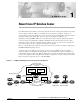
Chapter 1 About Cisco IP Solution Center Overview of ISC Figure 1-3 Access Domain Assigned Service Provider network 89998 IP Solution Center Network Management subnet Management PE Management VPN PE Access domain CLE-1 CLE-2 Management CE Service provider MPLS core PE PE-POP 1 PE PE-POP 2 CE 2 New York CE 2 Chicago 2. All the network elements have been discovered during the Autodiscovery process, as well as the network topology (connectivity between sites). 3.
Chapter 1 About Cisco IP Solution Center Overview of ISC • Route Distinguisher (RD) pool: The IP subnets advertised by the CE routers to the PE routers are augmented with a 64-bit prefix called a route distinguisher (RD) to make them unique. The resulting 96-bit addresses are then exchanged between the PEs, using a special address family of Multiprotocol BGP (referred to as MP-BGP). The RD pool is a pool of 64-bit RD values that ISC uses to make sure the IP addresses in the network are unique.
Chapter 1 About Cisco IP Solution Center Overview of ISC • VRF configuration (export map, import map, maximum number of routes, VRF and RD override, and so forth) • Choice of joining the VPN as hub or spoke • Choice of interfaces on the PE, CE, and intermediate network devices All the provisioning parameters can be made editable for a service operator who will deploy the service. A service policy is defined by a network operator and used by a service operator.
Chapter 1 About Cisco IP Solution Center Overview of ISC Figure 1-4 Defining the User Role ISC Service Request States WAIT DEPLOY FAILED DEPLOY Provisioning States FAILED AUDIT Auditing States PENDING DEPLOYED FUNCTIONAL INVALID CLOSED LOST BROKEN 93827 REQUESTED The permissions to Create, View, Modify, and Delete are enforced for the following resources: • Persistent task • MPLS policy • SAA probe • MPLS service request • Workflow • Layer 2 VPN policy • Device • Layer 2 VPN
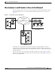
Chapter 1 About Cisco IP Solution Center The Customer’s and Provider’s View of the Network The Customer’s and Provider’s View of the Network From the customer’s point of view, they see their internal routers communicating with their customer edge routers (CEs) from one site to another through a VPN managed by the service provider (see Figure 1-5). Figure 1-5 The Customer’s View of the Network Service provider network CE CE Gadgets, Inc's VPN Gadgets, Inc. New York City Gadgets, Inc.
Chapter 1 About Cisco IP Solution Center The Customer’s and Provider’s View of the Network Figure 1-6 Service Provider’s View of the Network VPN 10 CE Gadgets, Inc. Seattle VPN 10 Service provider network BGP PE-1 BGP CE Gadgets, Inc. New York City PE-2 MPLS core BGP VPN 15 VPN 15 PE-3 VPN 10 VPN 15 CE Gizmos, Intl. San Francisco CE Gadgets, Inc. Chicago CE Gizmos, Intl. Berlin 28555 CE Gizmos, Intl.
Chapter 1 About Cisco IP Solution Center The Customer’s and Provider’s View of the Network A Multi-VRF CE is unlike a CE in that there is no label exchange, no LDP adjacency, and no labeled packet flow between the PE and the CE. Multi-VRF CE routers use VRF interfaces to form a VLAN-like configuration on the customer side. Each VRF on the Multi-VRF CE router is mapped to a VRF on the PE router. Figure 1-7 illustrates one method in which a Multi-VRF CE can be used.
Chapter 1 About Cisco IP Solution Center Using Templates to Customize Configuration Files Mapping IPsec Tunnels to MPLS VPNs Provisioning network-based IPsec VPNs in order to map IPsec tunnels to MPLS VPNs involves both MPLS and IPsec services in IP Solutions Center. Thus, it is necessary to create both MPLS and IPsec policies, as well as MPLS and IPsec service requests. For details, see Chapter 6, “Mapping IPsec to MPLS VPN.” The IPsec terminating router resides on the service provider premises.
Chapter 1 About Cisco IP Solution Center Using Templates to Customize Configuration Files The template files and data files are in XML format. The template file, its data files, and all template configuration file files are mapped to a single directory. • ISC creates the initial ISC configlet. Through the Template Manager, you can create a template configuration file.
Chapter 1 About Cisco IP Solution Center About MPLS VPNs • Audit Existing Services: Checks and evaluates configuration of deployed service to see if the service is still in effect. • Audit Routing Reports: Checks the VRF for the VPN on the PE. This report also checks if VPN connectivity is operational by evaluating reachability of the network devices in the VPN. About MPLS VPNs At its simplest, a virtual private network (VPN) is a collection of sites that share the same routing table.
Chapter 1 About Cisco IP Solution Center About MPLS VPNs Characteristics of MPLS VPNs MPLS VPNs have the following characteristics: • Multiprotocol Border Gateway Protocol-Multiprotocol (MP-BGP) extensions are used to encode customer IPv4 address prefixes into unique VPN-IPv4 Network Layer Reachability Information (NLRI) values. NLRI refers to a destination address in MP-BGP, so NLRI is considered “one routing unit.
Chapter 1 About Cisco IP Solution Center About MPLS VPNs VPN Routing and Forwarding Tables (VRFs) The VPN routing and forwarding table (VRF) is a key element in the MPLS VPN technology. VRFs exist on PEs only (except in the case of a Multi-VRF CE). A VRF is a routing table instance, and more than one VRF can exist on a PE. A VPN can contain one or more VRFs on a PE. The VRF contains routes that should be available to a particular set of sites.
Chapter 1 About Cisco IP Solution Center About MPLS VPNs VRFs for Sites in Multiple VPNs Site 1 VPN A ip vrf site1 rd 100:1 route-target export 100:1 route-target import 100:1 ip vrf site2 rd 100:2 route-target export 100:2 route-target import 100:2 route-target import 100:1 route-target export 100:1 VRF for site 1 (100:1) Site 1 routes Site 2 routes Site 1 Site 4 VPN B Site 2 Site 3 VPN C Multihop MP-iBGP P P PE1 PE2 VRF for site 2 (100:2) Site 1 routes Site 2 routes Site 3 routes VRF for si
Chapter 1 About Cisco IP Solution Center About MPLS VPNs • The MPLS VPN backbone relies on the appropriate Interior Gateway Protocol (IGP) that is configured for MPLS, for example, EIGRP, or OSPF. When you issue a show ip route command on a PE, you see the IGP-derived routes connecting the PEs together. Contrast that with the show ip route vrf VRF_name command, which displays routes connecting customer sites in a particular VPN.
Chapter 1 About Cisco IP Solution Center About MPLS VPNs ISC chooses route target values by default, but you can override the automatically assigned RT values if necessary when you first define a CERC in the ISC software (see the “Defining CE Routing Communities” section on page 4-5). Route Target Communities The mechanism by which MPLS VPN controls distribution of VPN routing information is through the VPN route-target extended MP-BGP communities.
Chapter 1 About Cisco IP Solution Center About MPLS VPNs ISC supports multiple CEs per site and multiple sites connected to the same PE. Each CERC has unique route targets (RT), route distinguisher (RD) and VRF naming. After provisioning a CERC, it is a good idea to run the audit reports to verify the CERC deployment and view the topologies created by the service requests. The product supports linking two or more CE routing communities in the same VPN.
Chapter 1 About Cisco IP Solution Center Security Requirements for MPLS VPNs Security Requirements for MPLS VPNs This section discusses the security requirements for MPLS VPN architectures. This section concentrates on protecting the core network against attacks from the “outside,” that is, the Internet and connected VPNs.
Chapter 1 About Cisco IP Solution Center Security Requirements for MPLS VPNs Given addressing and routing separation across an MPLS core network, MPLS offers in this respect the same security as comparable Layer 2 VPNs, such as ATM or Frame Relay. It is not possible to intrude into other VPNs through the MPLS core, unless this has been configured specifically.
Chapter 1 About Cisco IP Solution Center Security Requirements for MPLS VPNs Resistance to Attacks It is not possible to directly intrude into other VPNs. However, it is possible to attack the MPLS core, and try to attack other VPNs from there. There are two basic ways the MPLS core can be attacked: • Attacking the PE routers directly.
Chapter 1 About Cisco IP Solution Center Security Requirements for MPLS VPNs In practice, access to the PE router over the CE-PE interface can be limited to the required routing protocol by using access control lists (ACLs). This limits the point of attack to one routing protocol, for example BGP. A potential attack could send an extensive number of routes, or flood the PE router with routing updates. Both of these attacks could lead to a denial-of-service attack, however, not to an intrusion attack.
Chapter 1 About Cisco IP Solution Center Security Requirements for MPLS VPNs For security reasons, a PE router should never accept a packet with a label from a CE router. Cisco routers implementation is such that packets that arrive on a CE interface with a label are dropped. Thus, it is not possible to insert fake labels because no labels are accepted. There remains the possibility to spoof the IP address of a packet that is being sent to the MPLS core.
Chapter 1 About Cisco IP Solution Center Security Requirements for MPLS VPNs • PE-P link: use LDP MD5 authentication • P-P This prevents attackers from spoofing a peer router and introducing bogus routing information. Secure management is particularly important regarding configuration files, which often contain shared secrets in clear text (for example for routing protocol authentication).
Chapter 1 About Cisco IP Solution Center Security Requirements for MPLS VPNs From a security point of view, the merged VPNs behave like one logical VPN, and the security mechanisms described above apply now between the merged VPN and other VPNs. The merged VPN must have unique address space internally, but further VPNs can use the same address space without interference. Packets from and to the merged VPNs cannot be routed to other VPNs.
Chapter 1 About Cisco IP Solution Center Security Requirements for MPLS VPNs The forwarding table for a PE contains only address entries for members of the same VPN. The PE rejects requests for addresses not listed in its forwarding table. By implementing a logically separate forwarding table for each VPN, each VPN itself becomes a private, connectionless network built on a shared infrastructure. IP limits the size of an address to 32 bits in the packet header.
Chapter 1 About Cisco IP Solution Center Security Requirements for MPLS VPNs • Layer 2 VPN Service • MPLS VPN Service • Inventory • IPsec VPN Service • FireWall Service • NAT Service • SLA • Deployment Flow Engine • Discovery • Workflow NBI Benefits The benefits of the north-bound interface are as follows: • Supports ISC services and inventory • XML-based management interface • Web-based • Human-readable encoding • Initial transport support is HTTP/SOAP • API based on domain
Chapter 1 About Cisco IP Solution Center Security Requirements for MPLS VPNs • The Processing server can be added dynamically. The Watchdog will discover their existence when you start up ISC. • Each Collection server is responsible for a set of collection zones. Each zone has one Collection Server. • Both Processing servers and Collection servers failover to the Master server automatically. • Each device belongs to a zone, but a device can be relocated to a different zone as needed.
Chapter 1 About Cisco IP Solution Center The Four-Tier System Architecture Figure 1-12 Redundant Load Balancing Configuration Service Provider network Layer 3 router (r-1) 192.168.0.2 active 192.168.0.1 (HSRP floating IP) Layer 3 router (r-2) 192.168.0.3 standby 192.168.0.10 (floating IP) 192.168.0.200 (floating IP) Layer 2 switch (sw-1) Web server (ws-1) 192.168.0.100 Load Balancer (lb-2) 192.168.0.12 Trunk Layer 2 switch (sw-1) Web server Web server (ws-3) (ws-2) 192.168.0.101 192.168.0.
Chapter 1 About Cisco IP Solution Center The Four-Tier System Architecture • Control tier The Control Tier consists of the ISC Repository (a relational database) and the task scheduling and distribution system. In ISC, there is only one Control tier machine, and it is called the master machine. The master machine is the nerve center of the whole infrastructure; you can consider it to be identical to the ISC workstation itself. All vital information is stored in the Repository of the master machine.