Cisco CRS-1Carrier Routing System 8-Slot Line Card Chassis Site Planning Guide March 2008 Americas Headquarters Cisco Systems, Inc. 170 West Tasman Drive San Jose, CA 95134-1706 USA http://www.cisco.
THE SPECIFICATIONS AND INFORMATION REGARDING THE PRODUCTS IN THIS MANUAL ARE SUBJECT TO CHANGE WITHOUT NOTICE. ALL STATEMENTS, INFORMATION, AND RECOMMENDATIONS IN THIS MANUAL ARE BELIEVED TO BE ACCURATE BUT ARE PRESENTED WITHOUT WARRANTY OF ANY KIND, EXPRESS OR IMPLIED. USERS MUST TAKE FULL RESPONSIBILITY FOR THEIR APPLICATION OF ANY PRODUCTS.
C O N T E N T S Preface CHAPTER 1 v Cisco CRS-1 Carrier Routing System 1-1 The Cisco CRS-1 8-Slot Line Card Chassis Chassis Components 1-3 Chassis Slot Numbers 1-4 CHAPTER 2 Power and Cooling 1-2 2-1 Chassis Power System 2-1 General Power and Grounding Requirements DC Power Requirements 2-3 DC Input Power and Ground Cables 2-2 2-3 AC Power Requirements 2-6 AC PDU Wiring 2-7 Supplemental Bonding and Grounding Chassis Airflow 2-10 Facility Cooling Requirements CHAPTER 3 2-10 Technical a
Contents Route Processor Cables 4-7 PLIM Interface Cables 4-7 Custom Cables 4-7 Noise Control 4-8 Cisco Installation Services 4-8 System Testing, Certification, and Warranties APPENDIX APPENDIX A B Site Planning Guidelines A-1 Site Planning Checklist A-1 Preliminary Site Survey A-2 4-8 Product IDs for the Cisco CRS-1 8-Slot Line Card Chassis Cisco CRS-1 8-Slot Line Card Chassis Component Product IDs Optional MSC, PLIM, SIP, and SPA Product IDs B-1 B-1 B-3 INDEX Cisco CRS-1 Carrier Routi
Preface This site planning guide describes how to plan and prepare your site facilities for the installation of a Cisco CRS-1 Carrier Routing System 8-Slot Line Card Chassis (also referred to in this document as the “Cisco CRS-1 8-slot line card chassis”). The guide provides a brief description of the chassis and its components, and basic site facilities requirements.
Preface • Appendix B, “Product IDs for the Cisco CRS-1 8-Slot Line Card Chassis,” provides information about how to order the Cisco CRS-1 8-Slot Line Card Chassis components. Document Conventions This guide uses the following conventions: Caution Note Means reader be careful. You are capable of doing something that might result in equipment damage or loss of data. Means reader take note. Notes contain helpful suggestions or references to materials not contained in this manual.
Preface Changes to This Document lists the technical changes made to this document since it was first printed. Table 1 Changes to This Document Revision Date Change Summary OL-5802-06 February 2008 Minor editorial changes. OL-5802-05 June 2007 This revision updates the two-pole DC power requirements. OL-5802-04 June 2006 The front and rear clearance values for installation, service, and airflow have been updated in Chapter 4, “Site Planning Considerations.
Preface Cisco CRS-1 Carrier Routing System 8-Slot Line Card Chassis Site Planning Guide viii OL-5802-06
CH A P T E R 1 Cisco CRS-1 Carrier Routing System This site planning guide describes how to plan and prepare your site facilities for the installation of a Cisco CRS-1 Carrier Routing System 8-Slot Line Card Chassis (also referred to in this document as the “Cisco CRS-1 8-slot line card chassis”). The guide provides a brief description of the chassis and its components, and basic site facilities requirements.
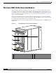
Chapter 1 Cisco CRS-1 Carrier Routing System The Cisco CRS-1 8-Slot Line Card Chassis The Cisco CRS-1 8-Slot Line Card Chassis The Cisco CRS-1 8-slot line card chassis is the main component of the Cisco CRS-1. The chassis is a mechanical enclosure that contains a chassis midplane. The midplane holds the system modular services cards (MSCs), their associated physical layer interface modules (PLIMs), and switch fabric cards. The chassis is mounted in a 19-inch equipment rack.
Chapter 1 Cisco CRS-1 Carrier Routing System The Cisco CRS-1 8-Slot Line Card Chassis Figure 1-2 Rear (MSC) View of the 8-Slot Line Card Chassis 1 2 3 4 5 122776 6 1 Upper fan tray (beneath cover) 4 MSC slots 2 Chassis vertical mounting brackets 5 Lower fan tray 3 Switch fabric card (half-height) slots 6 Power distribution units (PDUs) Chassis Components The Cisco CRS-1 8-slot line card chassis contains the following components: • As many as eight modular services cards (MSCs), also
Chapter 1 Cisco CRS-1 Carrier Routing System The Cisco CRS-1 8-Slot Line Card Chassis – 10-Gigabit Ethernet (GE. Available in long-reach (LR) optics. This PLIM supports pluggable optics, and can be configured with 1 to 8 ports. – Cisco CRS-1 SPA Interface Processor-800. Occupies one physical-layer-interface-module (PLIM) slot on the Cisco CRS-1 16- and 8-Slot Line Card Chassis. Supports six normal-height SPAs or three double-height SPAs or any combination in between. • A chassis midplane.
Chapter 1 Cisco CRS-1 Carrier Routing System The Cisco CRS-1 8-Slot Line Card Chassis Figure 1-3 Cisco CRS-1 8-Slot Line Card Chassis Slot Numbers FAN 0 0 1 2 3 SM 1 SM 0 4 5 6 7 7 6 5 4 RP 1 RP 0 3 2 1 0 SM 3 SM 2 122777 FAN 1 As shown, the front (PLIM) side of the chassis has the following card slots: • Eight PLIM slots (left to right: 0, 1, 2, 3...
Chapter 1 Cisco CRS-1 Carrier Routing System The Cisco CRS-1 8-Slot Line Card Chassis Cisco CRS-1 Carrier Routing System 8-Slot Line Card Chassis Site Planning Guide 1-6 OL-5802-06
CH A P T E R 2 Power and Cooling This chapter describes the Cisco CRS-1 Carrier Routing System 8-Slot Line Card Chassis power and cooling systems. It also provides the power and grounding and cooling requirements for the installation site to help you plan the site facilities for the system. The Cisco CRS-1 Carrier Routing System 8-Slot Line Card Chassis System Description provides detailed information about these components.
Chapter 2 Power and Cooling General Power and Grounding Requirements • Note An AC-powered chassis requires 8,750 watts of AC input power. These power requirements are for a fully loaded chassis with eight PLIMs. A chassis with six or seven PLIMs uses slightly less power. However, it is a good idea to allocate this much power for each chassis to ensure that enough power is available for future system expansion.
Chapter 2 Power and Cooling DC Power Requirements DC Power Requirements A DC-powered line card chassis contains two DC-input power distribution units (PDUs) and two DC power entry modules (PEMs). Each DC PDU is connected to three DC power inputs and contains a single 7500-watt DC PEM that is field replaceable. Input DC power enters the PDU and is passed to the PEM, which provides power to the components in the chassis. Each PEM has its own circuit breaker.
Chapter 2 Power and Cooling DC Power Requirements Each DC input power cable is terminated at the PDU by a cable lug. The cable lugs must be dual-hole, and have a 45-degree angle tongue. They must be able to fit over 1/4-inch terminal studs at 0.625-inch (15.88-mm) centers. For example, you could terminate a 2-AWG power cable with a cable lug, such as Panduit part number LCC2-14AWH-Q (Cisco part number 32-0677-01) or equivalent (see Figure 2-1).
Chapter 2 Power and Cooling DC Power Requirements Figure 2-2 DC Earth Ground Cable Lug All measurements in inches 2.24 End View 0.48 Ø 0.267 2 holes 0.63 0.37 0.08 25527 Crimp area 0.25 Figure 2-3 shows the DC input power cables connected to the DC PDU terminal studs. Figure 2-3 DC PDU Power Cable Connections 129533 1 1 Each set of cables (RTN and –48V/–60V) is a single VDC input. Note When wiring the PDU, be sure to attach the ground wire first (shown above on the far left side of PDU).
Chapter 2 Power and Cooling AC Power Requirements Caution Although reverse polarity should not damage the DC power system, you should correct a reverse polarity condition immediately. AC Power Requirements An AC-powered line card chassis contains two AC power distribution units (PDUs) and two AC rectifier modules. Each AC PDU is connected to an input AC power source and holds a single 7500-watt AC rectifier. Input AC power enters the PDU and is passed to the rectifier.
Chapter 2 Power and Cooling AC Power Requirements To AC outlet 116877 Figure 2-5 AC Wye Power Cord Plug To AC outlet 116876 Figure 2-4 AC Delta Power Cord Plug For detailed AC power specifications, see the “Line Card Chassis Specifications” section on page 3-1. In addition, the next section “AC PDU Wiring” describes the 3-phase wiring for AC Delta and Wye configurations.
Chapter 2 Power and Cooling AC Power Requirements Figure 2-6 AC Delta PDU Wiring Plugs into L15-30R receptacle 200 to 240 VAC, 30 A, 3-phase 2.5 po -kW mo wer d No ule .1 Phase X Phase Y Phase Z -kW 2.5 wer po ule d mo o. 2 N Safety Ground 122782 2.5-kW power module No. 3 AC Wye 3-Phase Wiring Figure 2-7 shows a PDU wired for AC Wye 3-phase power. As shown, input AC power is routed to three internal 2.5-kW power modules in the rectifier, where it is converted into DC power (nominal 54.
Chapter 2 Power and Cooling Supplemental Bonding and Grounding Supplemental Bonding and Grounding The 8-slot line card chassis has a safety earth ground connection as part of the power cabling to the PDUs. The chassis also has supplemental bonding and grounding points (two threaded ground inserts) that you can use to connect the router to the central office ground system or interior equipment grounding system.
Chapter 2 Power and Cooling Chassis Airflow Chassis Airflow The Cisco CRS-1 8-slot line card chassis has two fan trays, with three fans each, that cool the chassis card cages. Cool air flows in at the bottom front of the chassis and flows through the chassis card cages and through the fans in the fan trays before being exhausted through the bottom rear of the chassis (see Figure 2-9).
Chapter 2 Power and Cooling Facility Cooling Requirements Heat dissipation and external cooling requirements for the 8-slot line card chassis are as follows: • Heat dissipation: 27,350 BTUs per hour • External cooling requirements: 2.3 tons To ensure that the site provides the proper air circulation for the system: • Make certain that the site is as dust free as possible. Dusty environments can clog the air filter or power supply intake vents, reducing the cooling airflow through the system.
Chapter 2 Power and Cooling Facility Cooling Requirements Cisco CRS-1 Carrier Routing System 8-Slot Line Card Chassis Site Planning Guide 2-12 OL-5802-06
CH A P T E R 3 Technical and Environmental Specifications This chapter summarizes the technical and environmental specifications for the Cisco CRS-1 Carrier Routing System 8-Slot Line Card Chassis. It includes the following sections: • Line Card Chassis Specifications • Equipment Rack Specifications • Environmental Specifications Line Card Chassis Specifications The following table lists the system specifications for the Cisco CRS-1 8-slot line card chassis.
Chapter 3 Technical and Environmental Specifications Equipment Rack Specifications Table 3-1 8-Slot Line Card Chassis Component and Power Specifications (continued) Note Proper grounding is also required at the site to ensure that equipment is not damaged by lightning or power surges. Power Redundancy (2N) DC Three “A” battery plant feeds required for one PDU, and three “B” battery plant feeds required for the other PDU.
Chapter 3 Technical and Environmental Specifications Equipment Rack Specifications If you plan to install the chassis in your own four-post rack, make sure that the rack meets the specifications summarized in Table 3-2. Table 3-2 8-Slot Line Card Chassis and Equipment Rack Specifications 8-Slot Line Card Chassis Specifications Chassis Dimensions Height 38.5 in. (97.8 cm) Width 17.5 in. (44.5 cm) 18.9 in. (48.0 cm) mounting rail flange, outside to outside Depth 36.6 in. (93.
Chapter 3 Technical and Environmental Specifications Equipment Rack Specifications Table 3-2 8-Slot Line Card Chassis and Equipment Rack Specifications (continued) Load (weight) rating The rack must support the following weights and specifications: • 650 lb (294.8 kg) single chassis with full cosmetics • 1300 lb (589.7 kg) two chassis, each with full cosmetics • 95 lb (43.0 kg) or more for each chassis for cabling • Additional weight of other components in rack Note ANSI specification T1.
Chapter 3 Technical and Environmental Specifications Equipment Rack Specifications Table 3-2 8-Slot Line Card Chassis and Equipment Rack Specifications (continued) Equipment Rack Specifications (continued) Mounting Rails and Hardware Rail openings (aperture) Horizontal mounting rails • 17.75 in. (45.1 cm), side to side • 22.8 in. (57.9 cm), front to back (adjustable or fixed) The equipment rack should contain horizontal mounting rails to place the chassis on.
Chapter 3 Technical and Environmental Specifications Environmental Specifications Environmental Specifications The following table lists the environmental specifications for the Cisco CRS-1 8-slot line card chassis.
CH A P T E R 4 Site Planning Considerations This chapter describes the general considerations to address while planning for the installation of the Cisco CRS-1 8-Slot Line Card Chassis. It does not repeat the specifications in Chapter 3, but you should keep those specifications in mind as you plan for your system.
Chapter 4 Site Planning Considerations Tools Required for Installation • At least 48 inches (122 cm) of clearance exists between rows of equipment racks. This space is needed to access components in the chassis. Additional clearance may be necessary for installation. • Enough room exists for the system console terminal, and that the console cable is long enough to reach the routing system from the terminal.
Chapter 4 Site Planning Considerations Equipment Rack Considerations • Tape measure (optional) Equipment Rack Considerations A fully loaded Cisco CRS-1 8-slot line card chassis weighs 650 lb (294.8 kg). The chassis is mounted in a four-post rack. (See Figure 4-1.) To ensure safe installation and operation of the routing system, you must install the chassis in a four-post equipment rack that meets the specifications described in the “Equipment Rack Specifications” section on page 3-2.
Chapter 4 Site Planning Considerations Aisle Spacing and Maintenance Access Floor Plan Note We recommend that you use a scissor lift or similar lifting device to position the chassis in the rack and to hold the chassis in place while you bolt it to the rack. A forklift is not recommended for this purpose.
Chapter 4 Site Planning Considerations Aisle Spacing and Maintenance Access Floor Plan Figure 4-2 Typical Cisco CRS-1 8-Slot Line Card Chassis Floor Plan 36 in. (91.4 cm) Cisco CRS-1 8-slot line card chassis 40.4 in. (102.6 cm) Service access area: behind rear of chassis 36 in. (91.4 cm) 112.4 in. (285.
Chapter 4 Site Planning Considerations Power and Cooling Requirements Power and Cooling Requirements See Chapter 2, “Power and Cooling,” for information about the power and cooling systems on the 8-slot chassis and for information about the power and cooling requirements at the installation site. System Console A system console is required to configure the routing system for operation.
Chapter 4 Site Planning Considerations Cable Management Cable Management Bracket (Front of Chassis Only) 101818 Figure 4-3 Route Processor Cables As you consider system cabling, see Table 4-1 to determine the types of cables required to connect to ports on the route processor (RP). Table 4-1 Route Processor Cables RP Port Required Cable Type Ethernet management Shielded twisted-pair (STP) cable (Category 5 or better).
Chapter 4 Site Planning Considerations Noise Control Noise Control A routing system can generate large amounts of fan noise. The 8-slot line card chassis has some built-in noise reduction, such as fan speed control. If the routing system is installed in an environment where excessive noise could be harmful to personnel, some other noise reduction options could be attempted. Passive noise reduction could include the installation of foam panels to insulate the surrounding area from the noise.
A P P E N D I X A Site Planning Guidelines This appendix contains the following sections: • Site Planning Checklist • Preliminary Site Survey Site Planning Checklist Table A-1 lists the sequence of tasks to perform as you plan the installation of the routing system. Use the table as a checklist for all aspects of the installation. For information about a particular task, see the appropriate section of this site planning guide.
Appendix A Site Planning Guidelines Preliminary Site Survey Preliminary Site Survey Typically, you should complete a preliminary site survey before you plan a detailed site survey. This preliminary survey ensures that the basic system requirements have been completed or are underway before detailed plans for the site are completed. Table A-2 is a sample preliminary site survey.
Appendix A Site Planning Guidelines Preliminary Site Survey Table A-2 Sample Routing System Preliminary Site Survey (continued) Preliminary Site Survey Secondary Contact Name and title: Phone number: Mobile phone number: Fax number: Pager number: E-mail address: Delivery and Installation Constraints Is there a loading dock available to unload the equipment at this site? Is someone on site during working hours to accept delivery of the materials? If not, list the times this person is available.
Appendix A Site Planning Guidelines Preliminary Site Survey Table A-2 Sample Routing System Preliminary Site Survey (continued) Preliminary Site Survey Power Is DC or AC power available for each chassis? Is there a connection point on the panel for each chassis? Is a fuse access panel (FAP) available for the equipment? Provide a connection point on the FAP for each chassis. Will an FAP be installed in time for the routing system installation? Provide a date when the FAP will be installed.
Appendix A Site Planning Guidelines Preliminary Site Survey Table A-2 Sample Routing System Preliminary Site Survey (continued) Preliminary Site Survey Supported Data Interfaces Will the routing system be connected to OC-48/STM-16 POS circuits? How many ports? Will the routing system be connected to OC-192/STM-64 POS circuits? How many ports? Will the routing system be connected to OC-768/STM-256 POS circuits? How many ports? Will the routing system be connected to 10-Gigabit Ethernet (GE) circuits? Ho
Appendix A Site Planning Guidelines Preliminary Site Survey Cisco CRS-1 Carrier Routing System 8-Slot Line Card Chassis Site Planning Guide A-6 OL-5802-06
A P P E N D I X B Product IDs for the Cisco CRS-1 8-Slot Line Card Chassis This appendix provides information about the product IDs for components of the Cisco CRS-1 Carrier Routing System 8-Slot Line Card Chassis.
Appendix B Product IDs for the Cisco CRS-1 8-Slot Line Card Chassis Cisco CRS-1 8-Slot Line Card Chassis Component Product IDs Table B-1 8-Slot Routing System Component Product IDs (continued) Component Product ID Description Installation kit CRS-8-INSTALL-KT= Line card chassis installation kit (includes a set of horizontal shelf brackets, mounting screws, and other items) CRS-8-PWR-FILTER= Filters (five per pack) for AC rectifier and DC PEM AC Delta PDU CRS-8-LCC-PDU-ACD= Cisco CRS-1 AC Delt
Appendix B Product IDs for the Cisco CRS-1 8-Slot Line Card Chassis Optional MSC, PLIM, SIP, and SPA Product IDs Optional MSC, PLIM, SIP, and SPA Product IDs The following tables list the product IDs for the modular services cards (MSCs) and physical layer interface modules (PLIMs) available for the Cisco CRS-1 8-slot line card chassis.
Appendix B Product IDs for the Cisco CRS-1 8-Slot Line Card Chassis Optional MSC, PLIM, SIP, and SPA Product IDs Table B-4 SIP and SPA Component Product IDs Component Product ID Cisco CRS-1 SPA CRS1-SIP-800 Interface Processor-800 1-Port OC-192c/ STM64 POS/RPR XFP SPA SPA-OC192POS-XFP 4-Port OC-3c/STM-1 POS SPA SPA-4XOC3-POS 8-Port OC-12c/STM-4 Multirate POS SPA SPA-8XOC12-POS 8-Port Gigabit Ethernet SPA SPA-8X1GE Description Occupies one physical-layer- interfacemodule (PLIM) slot on the Ci
I N D EX PLIM interface Numerics power 10-GE PLIM B-3 RP 4-7 2-6, 2-9 4-7 chassis airflow (figure) A dimensions AC Delta PDU wiring (figure) acoustic noise, specifications 2-8 2-6 specifications 2-6 4-5 front view (figure) 1-2 rear view (figure) 2-8 2-10 airflow 4-3 1-4 product IDs (table) 3-2 AC Wye PDU wiring (figure) air filter floor plan (figure) midplane requirements 4-5 equipment rack installation (figure) 3-6 AC power cables 2-10 B-1 1-3 slot numbers (figure) 1-5
Index restricted system access 2-3 G safety extra-low voltage (SELV) requirements specifications grounding requirements 3-2 torque value for power connector screws dimensions, chassis 2-3 2-2, 2-9 2-5 4-5 H heat dissipation, specifications E humidity, specifications electrical codes 3-6 3-6 2-2 environmental specifications (table) 3-6 I equipment rack considerations overview impedance carriers 4-3 installation 4-3 specifications (table) Ethernet ports B-3 clearance distance 3-3
Index interface cables product IDs (table) supported front and back 4-7 overview B-3 1-1 physical dimensions 1-3 ports, CONSOLE and AUX PLIM types 4-6 power cables 1-4 3-3 1-3 power and grounding power requirements 2-6, 2-9 power system redundancy 2-1 product IDs 2-1, 2-6 slot numbers requirements weight 3-1 specifications (table) 3-1 B-1 1-4 switch fabric cards 2-2, 2-9 specifications 2-2, 2-9 1-4 3-3 See also chassis 3-1 product IDs chassis components MSCs and PLIMs
Index equipment rack specifications installation checklist MSC product IDs A-1 B-3 PLIM product IDs RP cables 3-3 B-3 4-7 site survey (sample) A-2 SPA Interface Processor-800 SPA product IDs B-4 B-4 temperature, specifications 3-6 torque value for power connector screws 2-5 V vibration, specifications 3-6 W weight, routing system 3-3 Cisco CRS-1 Carrier Routing System 8-Slot Line Card Chassis Site Planning Guide IN-4 OL-5802-06