
User Guide


11-6
Catalyst 6500 Series Switch Cisco IOS Software Configuration Guide—Release 12.1 E
78-14099-04
Chapter 11 Configuring Cisco IP Phone Support
Configuring Cisco IP Phone Support
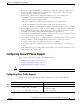
When configuring the way in which the Cisco IP Phone transmits voice traffic, note the following syntax
information:
• Enter a voice VLAN ID to send CDPv2 packets that configure the Cisco IP Phone to transmit voice
traffic in 802.1Q frames, tagged with the voice VLAN ID and a Layer 2 CoS value (the default is
5). Valid VLAN IDs are from 1 to 4094. The switch puts the 802.1Q voice traffic into the voice
VLAN.
• Enter the dot1p keyword to send CDPv2 packets that configure the Cisco IP Phone to transmit voice
traffic in 802.1p frames, tagged with VLAN ID 0 and a Layer 2 CoS value (the default is 5 for voice
traffic and 3 for voice control traffic). The switch puts the 802.1p voice traffic into the access VLAN.
• Enter the untagged keyword to send CDPv2 packets that configure the Cisco IP Phone to transmit
untagged voice traffic. The switch puts the untagged voice traffic into the access VLAN.
• Enter the none keyword to allow the Cisco IP Phone to use its own configuration and transmit
untagged voice traffic. The switch puts the untagged voice traffic into the access VLAN.
• In all configurations, the voice traffic carries a Layer 3 IP precedence value (the default is 5).
• Refer to Chapter 31, “Configuring PFC QoS,” for information about how to configure QoS.
• Refer to the “Configuring a LAN Interface as a Layer 2 Access Port” section on page 7-14 for
information about how to configure the port as a Layer 2 access port and configure the
access VLAN.
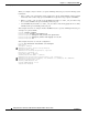
This example shows how to configure Fast Ethernet port 5/1 to send CDPv2 packets that tell the
Cisco IP Phone to use VLAN 101 as the voice VLAN:
Router# configure terminal
Router(config)# interface fastethernet 5/1
Router(config-if)# switchport voice vlan 101
Router(config-if)# exit
This example shows how to verify the configuration of Fast Ethernet port 5/1:
Router# show interfaces fastethernet 5/1 switchport
Name: Fa5/1
Switchport: Enabled
Administrative Mode: access
Operational Mode: access
Administrative Trunking Encapsulation: dot1q
Operational Trunking Encapsulation: dot1q
Negotiation of Trunking: off
Access Mode VLAN: 100
Voice VLAN: 101
Trunking Native Mode VLAN: 1 (default)
Administrative private-vlan host-association: none
Administrative private-vlan mapping: 900 ((Inactive)) 901 ((Inactive))
Operational private-vlan: none
Trunking VLANs Enabled: ALL
Pruning VLANs Enabled: 2-1001
Capture Mode Disabled
Capture VLANs Allowed: ALL
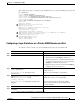
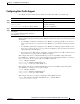
Step 3
Router(config)# end
Exits configuration mode.
Step 4
Router# show interfaces fastethernet slot/port
switchport
Router# show running-config interface
fastethernet slot/port
Verifies the configuration.
Command Purpose