
User Guide


14-8
Catalyst 6500 Series Switch Cisco IOS Software Configuration Guide—Release 12.1 E
78-14099-04
Chapter 14 Configuring IEEE 802.1Q Tunneling and Layer 2 Protocol Tunneling
Configuring Support for Layer 2 Protocol Tunneling
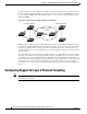
topology on switches 1, 2, and 3 without considering convergence parameters based on switches 4 and 5. To
provide a single spanning tree domain for the customer, a generic scheme to tunnel BPDUs was created
for control protocol PDUs (CDP, STP, and VTP). This process is referred to as Generic Bridge PDU
Tunneling (GBPT).
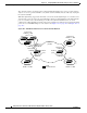
Figure 14-3 Layer 2 Protocol Tunneling Network Configuration
GBPT provides a scalable approach to PDU tunneling by software encapsulating the PDUs in the ingress
edge switches and then multicasting them in hardware. All switches inside the service provider network
treat these encapsulated frames as data packets and forward them to the other end. The egress edge
switch listens for these special encapsulated frames and deencapsulates them; they are then forwarded
out of the tunnel.
The encapsulation involves rewriting the destination media access control (MAC) address in the PDU.
An ingress edge switch rewrites the destination MAC address of the PDUs received on a Layer 2 tunnel
port with the Cisco proprietary multicast address (01-00-0c-cd-cd-d0). The PDU is then flooded to the
native VLAN of the Layer 2 tunnel port. If you enable Layer 2 protocol tunneling on a port, PDUs of an
enabled protocol are not sent out. If you disable Layer 2 protocol tunneling on a port, the disabled
protocols behave the same way they were behaving before Layer 2 protocol tunneling was disabled on
the port.
Configuring Support for Layer 2 Protocol Tunneling
Note Encapsulated PDUs received by an 802.1Q tunnel port are transmitted from other tunnel ports in the
same VLAN on the switch.
Service provider
network
Customer switches Customer switches
Edge
switches
Switch 1
Switch 3
Switch 4
Switch 5
Switch 2 Switch A Switch B
77066