
User Guide


15-12
Catalyst 6500 Series Switch Cisco IOS Software Configuration Guide—Release 12.1 E
78-14099-04
Chapter 15 Configuring STP and IEEE 802.1s MST
Understanding How STP Works
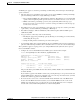
Disabled State
A Layer 2 LAN port in the disabled state does not participate in frame forwarding or STP, as shown in
Figure 15-7. A Layer 2 LAN port in the disabled state is virtually nonoperational.
Figure 15-7 Interface 2 in Disabled State
A disabled Layer 2 LAN port performs as follows:
• Discards frames received from the attached segment.
• Discards frames switched from another port for forwarding.
• Does not incorporate end station location into its address database. (There is no learning, so there is
no address database update.)
• Does not receive BPDUs.
• Does not receive BPDUs for transmission from the system module.
STP and IEEE 802.1Q Trunks
802.1Q trunks impose some limitations on the STP strategy for a network. In a network of Cisco network
devices connected through 802.1Q trunks, the network devices maintain one instance of STP for each
VLAN allowed on the trunks. However, non-Cisco 802.1Q network devices maintain only one instance
of STP for all VLANs allowed on the trunks.
When you connect a Cisco network device to a non-Cisco device through an 802.1Q trunk, the Cisco
network device combines the STP instance of the 802.1Q VLAN of the trunk with the STP instance of
the non-Cisco 802.1Q network device. However, all per-VLAN STP information is maintained by Cisco
network devices separated by a cloud of non-Cisco 802.1Q network devices. The non-Cisco 802.1Q
cloud separating the Cisco network devices is treated as a single trunk link between the network devices.
For more information on 802.1Q trunks, see Chapter 7, “Configuring LAN Ports for Layer 2 Switching.”
Filtering
database
Frame
forwarding
System
module
Port 1
BPDUs
All segment
frames
All segment
frames
Forwarding
Disabled
Station
addresses
Network
management
and data frames
Port 2
S5696
Network
management
frames
Data
frames