
User Guide


15-16
Catalyst 6500 Series Switch Cisco IOS Software Configuration Guide—Release 12.1 E
78-14099-04
Chapter 15 Configuring STP and IEEE 802.1s MST
Understanding How IEEE 802.1s MST Works
• MST establishes and maintains additional spanning trees within each MST region. These spanning
trees are referred to as MST instances (MSTIs). The IST is numbered 0, and the MSTIs are
numbered 1,2,3, and so on. Any MSTI is local to the MST region that is independent of MSTIs in
another region, even if the MST regions are interconnected. MST instances combine with the IST at
the boundary of MST regions to become the CST as follows:
–
Spanning tree information for an MSTI is contained in an MSTP record (M-record).
M-records are always encapsulated within MST BPDUs (MST BPDUs). The original spanning
trees computed by MSTP are called M-trees. M-trees are active only within the MST region.
M-trees merge with the IST at the boundary of the MST region and form the CST.
• MST provides interoperability with PVST+ by generating PVST+ BPDUs for the non-CST VLANs.
• MST supports some of the PVST+ extensions in MSTP as follows:
–
UplinkFast and BackboneFast are not available in MST mode; they are included in RSTP.
–
PortFast is supported.
–
BPDU filter and BPDU guard are supported in MST mode.
–
Loop guard and root guard are supported in MST. MST preserves the VLAN 1 disabled
functionality except that BPDUs are still transmitted in VLAN 1.
–
MST switches operate as if MAC reduction is enabled.
–
For private VLANs (PVLANs), secondary VLANs must be mapped to the same instance as the
primary.
MST-to-PVST Interoperability
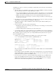
A virtual bridged LAN may contain interconnected regions of single spanning tree (SST) and MST
bridges. Figure 15-8 shows this relationship.
Figure 15-8 Network with Interconnected SST and MST Regions
MST
Region
MST
Region
SST
Region
SST
Region
F
F
F
F
F
F
R
F
F
F
F
F
F
F
B
B
B
B
B
r
r
r
r
r
r
r
b
b
F/f
= Forwarding
B/b = Blocking
R
= Root Bridge
r
= Root port
68285