
User Guide


31-21
Catalyst 6500 Series Switch Cisco IOS Software Configuration Guide—Release 12.1 E
78-14099-04
Chapter 31 Configuring PFC QoS
Understanding How PFC QoS Works
Attaching Policy Maps
You can configure each ingress LAN port for either physical port-based PFC QoS (default) or
VLAN-based PFC QoS (see the “Enabling VLAN-Based PFC QoS on Layer 2 LAN Ports” section on
page 31-52) and attach a policy map to the selected port (see the “Attaching a Policy Map to an Interface”
section on page 31-49).
On ports configured for port-based PFC QoS, you can attach a policy map to the ingress LAN port as
follows:
• On a nontrunk ingress LAN port configured for port-based PFC QoS, all traffic received through the
port is classified, marked, and policed according to the policy map attached to the port.
• On a trunking ingress LAN port configured for port-based PFC QoS, traffic in all VLANs received
through the port is classified, marked, and policed according to the policy map attached to the port.
On a nontrunk ingress LAN port configured for VLAN-based PFC QoS, traffic received through the port
is classified, marked, and policed according to the policy map attached to the port’s VLAN.
On a trunking ingress LAN port configured for VLAN-based PFC QoS, traffic received through the port
is classified, marked, and policed according to the policy map attached to the traffic’s VLAN.
You can attach policy maps to OSM ports.
Egress CoS and ToS Values
PFC QoS associates CoS and ToS values with traffic as specified by the trust state and policers in the
policy map (see the “Internal DSCP Values” section on page 31-17). The associated CoS and ToS are
used at the egress port (see the “LAN Egress Port Features” section on page 31-21).
LAN Egress Port Features
These sections describe how PFC QoS schedules traffic through the transmit queues based on CoS values
and uses CoS-value-based transmit-queue drop thresholds to avoid congestion in traffic transmitted from
egress LAN ports:
• Transmit Queues, page 31-21
• Scheduling and Congestion Avoidance, page 31-22
• Marking, page 31-24
Note Egress LAN port scheduling and congestion avoidance uses Layer 2 CoS values. Egress LAN port
marking writes Layer 2 CoS values into trunk traffic and the Layer 3 ToS byte into all IP traffic.
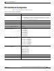
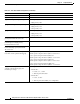
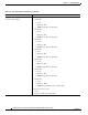
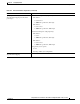
Transmit Queues
Enter the show queueing interface {ethernet | fastethernet | gigabitethernet | tengigabitethernet}
slot/port | include type command to see the queue structure of an egress LAN port.
The command displays one of the following:
• 2q2t indicates two standard queues, each with two configurable tail-drop thresholds
• 1p2q2t indicates one strict-priority queue and two standard queues, each with two configurable
WRED-drop thresholds.