B U R N E R S BRULEURS B R E N N E R QUEMADORES B R U C I AT O R I MANUAL FOR - INSTALLATION - OPERATION - MAINTENANCE LIGHT OIL BURNERS G18 G-.SP PG25 G-.SP PG30 G-.TN M03978CA Rev. 00 10/99 PARTE I: FOREWORD Page 2 INSTALLATION Page 4 PARTE II: OPERATION Page 11 PARTE III: MAINTENANCE Page 12 APPENDIX Page 18 Complying with EMC 89/336/CEE LV 73/23/CEE Technical Documentation CIB Unigas S.p.a.
PREFACE THIS MANUAL IS SUPPLIED AS AN INTEGRAL AND ESSENTIAL PART OF THE PRODUCT AND MUST BE DELIVERED TO THE USER. INFORMATION INCLUDED IN THIS SECTION ARE DEDICATED BOTH TO THE USER AND TO PERSONNEL FOLLOWING PRODUCT INSTALLATION AND MAINTENANCE. THE USER WILL FIND FURTHER INFORMATIONS ABOUT OPERATING AND USE RESTRICTIONS, IN THE SECOND SECTION OF THIS MANUAL. WE HIGHLY COMMEND TO READ IT. CAREFULLY KEEP THIS MANUAL FOR FUTURE REFERENCE.
) GENERAL INSTRUCTIONS DEPENDING ON FUEL USED 3B) FIRING WITH GAS, GASOIL OR OTHER FUELS 3A) ELECTRICAL CONNECTION GENERAL * For safety reasons the unit must be efficiently earthed and installed as required by current safety regulations. * It is vital that all saftey requirements are met. In case of any doubt, ask for an accurate inspection of electrics by qualified personnel, since the manufacturer cannot be held liable for damages that may be caused by failure to correctly earth the equipment.
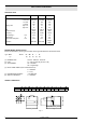
PART I: INSTALLATION MANUAL TECHNICAL DATA BURNER TYPE Input min kcal/h max kcal/h min kW max kW kg/h min. kg/h max. Oil firing rate Fuel Electrical supply Frequency Motor 2800 g/1' A absorbed Total power absorption kW A kW Operation G18 SP PG25 SP PG30 TN 90.300 180.000 105 209 9 18 light oil 230V 50 Hz 0.25 1.5 0.55 140.200 250.200 163 291 14 25 light oil 230V 50 Hz 0.37 2.2 0.87 Soft start Soft start 140.200 300.000 163 349 14 30 light oil 230V 50 Hz 0.37 2.2 0.
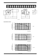
OVERALL DIMENSIONS PG25SP PG30SP A B BL C CL D E F G K H P M 515 155 345 660 850 267 260 520 133 290 125 155 M10 Fig. 1a Back pressure in combustion chamber mbar PERFORMANCE CURVES 1.8 1.6 1.4 1.2 1 0.8 0.6 0.4 0.2 0 Fig. 2 6 8 10 12 14 16 18 20 Back pressure in combustion chamber mbar Oil rate Kg/h 4 3 2 Fig. 3 1 0 -1 10 12 14 16 18 20 22 24 26 28 30 Back pressure in combustion chamber mbar Oil rate Kg/h 3 2.5 2 1.5 1 0.5 0 -0.5 -1 Fig.
MOUNTINGS AND CONNECTIONS The burners are despatched in cardboard packages. The packaging contains the following items: 1 burner; 2 flexible light oil tubes; 1 light oil filter; 1 gasket to be inserted between the burner and the boiler; 1 this manual, the Guarantee Certificate and the test certificate. To get rid of the burner’s packing and in the event of scrapping of the latter, follow the procedures laid down by current laws on disposal of materials.
G18SP PG25SP Fig. 5 PG30TN Fig. 5a Fig. 5b Fig.
SETTINGS Burners G18SP - PG25SP These burners are fitted with a double-regulation pump. The flame control device, a twin-stage one, after the pre-purgue stage, energized the valve EV1 and the burner starts up. After few seconds, the intervention of the second stage caused the energizing of the valve EV2, so the burner is feeded with a maximum pressure of about 18 bar.
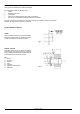
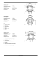
LIGHT OIL PUMPS SUNTEC AS57C Suction height: Advised value to prevent air separation from oil: Rated speed: Operation viscosity: Inlet pressure: 0.5 bar 0.35 bar max. 2850 rpm from 2 to 12 cSt max. 2 bar Fig. 7 DELTA VM2RL2 Suction height: Advised value to prevent air separation from oil: Rated speed: Operation viscosity: Inlet pressure: 0.5 bar 0.35 bar max. 3500 rpm from 1.5 to 50 cSt 0.7 - 1.
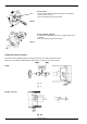
AIR FLOW ADJUSTMENT VBS + Burner G18SP Loose the screw VBS and rotate the air damper in the desired position, to set the air flow. At the end of settings, tight the screw VBS. Fig. 10 Burners PG25SP - PG30TN Loose the screw VBS and set the air flow, working directly on the air damper. At the end of settings, tight the screw VBS. Fig. 11 VBS COMBUSTION HEAD ADJUSTMENT The burner is factory-adjusted with the combustion head in the “max” position (maximum output).
PART II: OPERATION MANUAL LIMITATIONS OF USE THE BURNER IS AN APPLIANCE DESIGNED AND CONSTRUCTED TO OPERATE ONLY AFTER BEING CORRECTLY CONNECTED TO A HEAT GENERATOR (E.G. BOILER, HOT AIR GENERATOR, FURNACE, ETC.), ANY OTHER USE IS TO BE CONSIDERED IMPROPER AND THEREFORE DANGEROUS.
PART III: MAINTENANCE At least once a year carry out the following maintenance procedures. If servicing is on a seasonal basis, it is recommended at the end of the season; routine sevice should be carried out every months. Note: Any operation on the burner must be carried out with the main electricity switched off.
CHECK OF THE IONIZATION CURRENT To check the detector signal follow the prcedure shown in fig. 14. If the signal is not within the prescribed range, check the electrical contacts; check also that the combustion head is clean and the photoelectric sensor is correctly positioned. Replace it if necessary. TERMINAL BLOCK MC Scale µA DC Minimum current .7067 ( witt )Tj/TT3 1 Tf52.9337 (-0.0101 Tc-0.0061 Tw[flame:)-6187.8(65e Fig. 14 µT)]TJ -10 -1523 TD-0.0002 Tc-0.
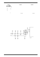
ELECTRICAL DIAGRAM code 01-369 BURNER G18SP CO Time counter EVG1 Light oil solenoid valve Ist stage EVG2 Light oil solenoid valve IInd stage F Fuse FR Photoresistor IL Main switch L1 Phase LF Burner operation light LB Burner lockout light LOA24/BOA64 Flame monitor device MA Power supply terminal block MV Fan motor N Neutral ST Thermostats or pressure switches TA Ignition transformer TS Boiler thermostat or pressure switch 1 - Electric supply 230V 50Hz 2N a.c.
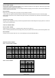
ELECTRICAL DIAGRAM code 04-574 BURNER PG30TN 1 - Electric supply 230V 50Hz 2N a.c.
SPARE PARTS BURNER G18SP POS. 1 2 3 4 5 6 7 8 9 10 13 14 15 16 17 18 16 DESCRIPTION HOUSING CONDENSER MOTOR FLAME CONTROL DEVICE LOA24 SOCKET FOR LOA24 SUPPORT BRACKET TRANSFORMER BURNER CASING FAN COMPLETE JOINT ATOMIZER NOZZLE ATOMIZER SUPPORT BOTTOM IGNITION CABLES IGNITION ELECTRODE CODE 3010019 6030004 2180009 2020445 2030409 2430004 2170106 2050228 2150004 254… 3020020 261.. 2280006 2010102 6050122 2080203 POS.
SPARE PARTS BURNERS PG25SP - PG30TN POS.
APPENDIX: COMPONENTS CHARACTERISTICS FLAME CONTROL DEVICE LANDIS LOA24 LIGHT OIL PUMPS Page 18 Page 19 LANDIS AUTOMATIC CONTROLLER LOA24 FOR LIGHT OIL BURNERS Use LOA... safety devices are intended for use in conjunction with QRB... photoresistors, for lighting and controlling low capacity forced air diesel burners with max. capacity 30 kg/h in accordance with standard DIN 4787. The One or two flames are lit, depending on electrical connections, with or without post-ignition.
Technical characteristics Voltage 220V-15%..240V+10% or 100V -15%...110V+10% Frequency 50...60Hz +/- 6% External fuse max.10A slow action Contact flow: - terminal 1 5A - terminal 3 5A (incl.capacity absorbed by motor and preheater) Terminal flow: - terminals 4, 5 &10 1A - terminals 6&7 2A - terminal 8 5A Absorbed cap 3VA Protection IP40 Premitted temp: operational -20...+60°C transport & storage -50...
Hydraulic data Operational pressure range SUNTEC AS oil pumps - Oil - Flow up to 75 1/h (c.600,000 kcal/h - 700 kW) - Twin-pipe system - Single-pipe system Technical data Mounting On flange or hub in acccordance with standards DIN 24220 and ISO/TC 109 SC 3 DP 5062F Threads round-headed in accordance with ISO R 228-NFE 03005(DIN2S9) Supply and return R 1/4" Delivery R 1/8" Pressure R 1/8" On cover R 1/8" Valve function Pressure control and cut out Filter area 34 cm2, 120 micron Shaft 8 mm in acc.
Operation The gear-set draws oil from the tank through the built-in filter and transfers it to the valve that regulates the oil pressure or tne nozzle line. All oil which does not go through the nozzle line will be dumped through the valve back to the return line or, if it is a one-pipe installation, back to the suction port in the gear-set. The hydraulic valve has a cut-off function besides regulating the nozzle pressure. Contrary to the AN pump, the valve has no bleed slot.
A B C D 1 2 3 Closed by-pass solenoid valve Opened by-pass solenoid valve Opened cut-off solenoid valve Closed cut-off solenoid valve Manometer plug To nozzle Shaft seal 4 5 6 7 8 9 10 11 Return to suction By-pass plug Return (twin pipe installation) Suction (twin pipe installation) Vacuum gauge plug Gear Hi-pressure regulator with control screw Lo-pressure regulator with control screw Oil under suction Oil under pressure By-passed oil returned to tank or to suction Twin pipe installation 22 APPENDIX
Via C. Colombo, 9 - 35011 Campodarsego (PD) Italy Tel. +39-049-9200944 - Fax +39-049-9200945-9201269 Internet: www.cibunigas.it - E mail: cibunigas@cibunigas.