Cisco IAD2430 Series Integrated Access Devices Hardware Installation Guide Americas Headquarters Cisco Systems, Inc. 170 West Tasman Drive San Jose, CA 95134-1706 USA http://www.cisco.
THE SPECIFICATIONS AND INFORMATION REGARDING THE PRODUCTS IN THIS MANUAL ARE SUBJECT TO CHANGE WITHOUT NOTICE. ALL STATEMENTS, INFORMATION, AND RECOMMENDATIONS IN THIS MANUAL ARE BELIEVED TO BE ACCURATE BUT ARE PRESENTED WITHOUT WARRANTY OF ANY KIND, EXPRESS OR IMPLIED. USERS MUST TAKE FULL RESPONSIBILITY FOR THEIR APPLICATION OF ANY PRODUCTS.
CONTENTS Preface vii Audience vii Organization vii Conventions viii Safety Warnings viii Warning Definition ix Product Serial Number Location Accessibility xiv xv Related Documentation xvi Obtaining Documentation and Submitting a Service Request CHAPTER 1 Overview of Cisco IAD2430 Series IADs xvi 1 Overview 1 Cisco IAD2430-24FXS IAD 3 Cisco IAD2431-8FXS IAD 3 Cisco IAD2431-16FXS 4 Cisco IAD2431-1T1E1 IAD 4 Cisco IAD2432-24FXS IAD 5 Cisco IAD2435-8FXS IAD 5 Physical Description LEDs 6
Contents Deployment Options CHAPTER 2 13 Planning Your Installation 1 Location and Mounting Requirements 1 Temperature Control and Ventilation 1 Rack-Mounted Installation 1 Wall-Mounted Installation 2 Desktop Installation 2 Access to Chassis 2 Chassis Grounding 2 Power Source 2 Cable Types 3 Distance Limitations for Interface Cables 4 Fast Ethernet Maximum Distance 4 T1/E1-WAN Port Maximum Distances 4 Serial Port Maximum Distances (WIC/VIC Cards) 4 T1/E1-PBX Digital Voice Port Maximum Distances 6 FXS
Wall-Mounting the Cisco IAD2435 IADs Desktop-Mounting the Chassis 14 Setting the Cisco IAD2435 on a Desktop Installing the Ground Connection Installing a WAN or Voice Card 14 14 17 Connecting Cables 18 LAN and Power Cables 19 Connecting the Input Power 21 Cable 21 Procedure 21 Connecting Input Power on the Cisco IAD2435 IAD 21 Connecting the Console Port to a PC or an ASCII Terminal 22 Cable 22 Procedure 22 Connecting the Auxiliary Port to a Modem 23 Cable 23 Procedure 23 Connecting the Fast Ethernet Po
Contents Remote Terminal Connections (If Applicable) 31 Connecting to a Modem 32 Connecting to a Remote PC 32 Connecting to a Remote ASCII Terminal 32 Connecting Backup Power 33 Connecting a Backup Battery to a DC-Powered IAD 33 Connecting an Uninteruptible Power Supply UPS to an AC-Powered Cisco IAD2430 Series IAD CHAPTER 4 Powering On Cisco IAD2430 Series IADs Checklist for Power-On Power-On Procedure 1 1 1 Initial Configuration Procedures 2 Cisco IOS CLI 3 Setup Command Facility 4 Manual Configura
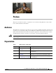
Preface This preface describes the audience, organization, and conventions of this publication, and describes how to obtain additional documentation. Audience This publication is designed for people who have some experience installing networking equipment such as routers, servers, and switches.
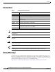
Preface Conventions Conventions Table 2 Installation Guide Conventions Convention Description boldface font Commands and keywords. italic font Variables for which you supply values. [ Keywords or arguments that appear within square brackets are optional. ] {x | y | z} A choice of required keywords appears in braces separated by vertical bars. You must select one. screen font Examples of information displayed on the screen. boldface screen Examples of information you must enter.
Preface Safety Warnings Warning Definition Warning IMPORTANT SAFETY INSTRUCTIONS This warning symbol means danger. You are in a situation that could cause bodily injury. Before you work on any equipment, be aware of the hazards involved with electrical circuitry and be familiar with standard practices for preventing accidents. To see translations of the warnings that appear in this publication, refer to the translated safety warnings that accompanied this device.
Preface Safety Warnings Avvertenza IMPORTANTI ISTRUZIONI SULLA SICUREZZA Questo simbolo di avvertenza indica un pericolo. La situazione potrebbe causare infortuni alle persone. Prima di intervenire su qualsiasi apparecchiatura, occorre essere al corrente dei pericoli relativi ai circuiti elettrici e conoscere le procedure standard per la prevenzione di incidenti. Per le traduzioni delle avvertenze riportate in questo documento, vedere le avvertenze di sicurezza che accompagnano questo dispositivo.
Preface Safety Warnings Cisco IAD2430 Series Integrated Access Devices Hardware Installation Guide OL-4234-06 xi
Preface Safety Warnings Aviso INSTRUÇÕES IMPORTANTES DE SEGURANÇA Este símbolo de aviso significa perigo. Você se encontra em uma situação em que há risco de lesões corporais. Antes de trabalhar com qualquer equipamento, esteja ciente dos riscos que envolvem os circuitos elétricos e familiarize-se com as práticas padrão de prevenção de acidentes. Use o número da declaração fornecido ao final de cada aviso para localizar sua tradução nos avisos de segurança traduzidos que acompanham o dispositivo.
Preface Safety Warnings Cisco IAD2430 Series Integrated Access Devices Hardware Installation Guide OL-4234-06 xiii
Preface Product Serial Number Location Warning Only trained and qualified personnel should be allowed to install, replace, or service this equipment. Statement 1030 Warning Do not use this product near water; for example, near a bath tub, wash bowl, kitchen sink or laundry tub, in a wet basement, or near a swimming pool. Statement 1035 Warning Never install telephone jacks in wet locations unless the jack is specifically designed for wet locations.
Preface Accessibility Figure 0-1 Serial Number Location on Cisco IAD2430 Series Routers AAA NNN NXX XX IAD2431 103054 -8FXS AAANNNNXXXX Figure 0-2 Serial Number Location on Cisco IAD2435-8FXS Routers Cisco 11 character label 188239, 781-00606-01 SN: AAANNNNXXXX Accessibility These integrated access devices can be configured using the Cisco command-line interface (CLI). The CLI conforms to code 508 because it is text based and it relies on a keyboard for navigation.
Preface Related Documentation Related Documentation The Cisco IOS software running your Cisco integrated access device includes extensive features and functionality. For information that is beyond the scope of this document, or for additional information, use the resources listed in Table 3 on page xvi. Timesaver Table 3 Make sure that you have access to the documents listed in Table 3.
CH A P T E R 1 Overview of Cisco IAD2430 Series IADs This chapter provides a brief description of Cisco IAD2430 series integrated access devices (IADs) and contains the following sections: • Overview, page 1-1 • Physical Description, page 1-6 • LEDs, page 1-7 • Chassis Grounding, page 1-9 • Memory, page 1-9 • Port Numbering Conventions, page 1-9 • Specifications, page 1-10 • Software Elements, page 1-10 • Interfaces and Service Capabilities, page 1-11 • Deployment Options, page 1-13 Ov
Chapter 1 Overview of Cisco IAD2430 Series IADs Overview Figure 1-1 Cisco IAD2430 Series IADs Front Panel 2400 88839 CISCO IAD Figure 1-2 0/0 FE 0/1 CD T1/E1 AL 2/0 2/1 2/2 2/3 FXS 2/4 2/5 2/6 Cisco IAD2 400 2/7 231872 OK Cisco IAD2435 Series IADs Front Panel SERIES The Cisco IAD2430 series IADs support the following interfaces: • 10/100BASE-T LAN connection • T1/E1 port connections • RJ-21 analog voice interface • WAN interface card/voice interface card (WIC/VIC) options •
Chapter 1 Overview of Cisco IAD2430 Series IADs Overview Warning Ultimate disposal of this product should be handled according to all national laws and regulations. Statement 1040 Cisco IAD2430-24FXS IAD The Cisco IAD2430-24FXS IAD provides 24 analog foreign exchange station (FXS) ports with two 10/100BASE-T ports.
Chapter 1 Overview of Cisco IAD2430 Series IADs Overview Figure 1-4 Cisco IAD2431-8FXS Chassis -8FXS 88825 IAD2431 Cisco IAD2431-16FXS The Cisco IAD2431-16FXS IAD (Figure 1-5) provides sixteen analog FXS ports with two 10/100BASE-T ports and two T1/E1 WAN ports.
Chapter 1 Overview of Cisco IAD2430 Series IADs Overview Figure 1-6 Cisco IAD2431-1T1E1 Chassis -1T1E1 88827 IAD2431 Cisco IAD2432-24FXS IAD The Cisco IAD2432-24FXS IAD (Figure 1-7) provides 24 analog FXS ports, two 10/100BASE-T ports, and two T1/E1 WAN ports.
Chapter 1 Overview of Cisco IAD2430 Series IADs Physical Description Figure 1-8 Cisco IAD2435-8FXS Chassis FXS IAD2435- 8FXS WAN et CONSOLE 231873 FastEthern T1/E1 0/1 0/0 AUX 12V DC SA Physical Description Figure 1-9 and Figure 1-10 show the function options of the two IAD243x chassis. All interface slots are on the back of the chassis.
Chapter 1 Overview of Cisco IAD2430 Series IADs LEDs Figure 1-10 Cisco IAD2435 Series IAD Back Panel Function Options FXS IAD2435- 8FXS WAN et CONSOLE 231879 FastEthern T1/E1 0/1 1 0/0 AUX 12V DC 2 3 4 5 SA 6 7 8 1 RJ-21 connector 2 T1/E1 WAN uplink 3 Fast Ethernet port 1 Fast Ethernet port 0 4 Serial port—console or auxiliary 5 Power connector 6 On/off switch 7 Chassis ground connection 8 Kensington security slot Note A Kensington security slot is located on the rout
Chapter 1 Overview of Cisco IAD2430 Series IADs LEDs Cisco IAD2400 Series LEDs (Cisco 2432-24FXS shown) 1 95007 Figure 1-11 2 3 4 No LED/Color Description 1 ACT—green Green indicates activity—when any of the 24 voice ports is active in a call (off hook) or when one of the analog ports is in use Status—green Green when accessing IAD 2 CF (Slot 0)—green Green when accessing read or write function 3 Link—green Indicates link activity 100—green 100BASE-T is active FDX—green Green when fu
Chapter 1 Overview of Cisco IAD2430 Series IADs Chassis Grounding No LED/Color LED Color and Description 1 PWR OK—green Off—no power Steady on—normal operation Slow blink—boot up phase or in ROMMON monitor mode 2 FE ports 0/1—green Off—No link Steady on—link Blinking—TXD/RXD data 3 T1/E1 (carrier detect)—green Off—no Carrier Detect Steady on—Carrier Detect Off—no Alarm condition Steady on—Alarm condition T1/E1 AL—Amber 4 FXS ports 0 through 7—green Off—On hook Steady On—Off hook Chassis Gro
Chapter 1 Overview of Cisco IAD2430 Series IADs Specifications Port numbering conventions for the Cisco IAD2435 series IAD are as follows: • Fast Ethernet ports are numbered 0 and 1, from left to right. • The controller T1/E1 port is numbered T1 0 or E1 0, from left to right. • FXS voice port numbering begins at 0 and reaches a maximum of 7, depending on the number of voice ports, from left to right.
Chapter 1 Overview of Cisco IAD2430 Series IADs Interfaces and Service Capabilities Manual Configuration When you install a Cisco IAD2430 series IAD, see the “Power-On Procedure” section on page 4-1 for the initial configuration. This configuration sets the basic communication parameters.
Chapter 1 Overview of Cisco IAD2430 Series IADs Interfaces and Service Capabilities Table 1-1 Cisco IAD2430 Series Interfaces and Service Capabilities Port Interface Configurations Console port 0/0 Auxiliary port 0/1 Interface To Services Supported Details EIA/TIA-232 asynchronous ASCII terminal serial (DCE) Personal computer Local administrative access RJ-45 physical interface EIA/TIA-232 asynchronous Modem serial (DTE) Remote administrative access RJ-45 physical interface Note Note Dat
Chapter 1 Overview of Cisco IAD2430 Series IADs Deployment Options Configuration Options The following interface options are available in Cisco IAD2430 series IADs: Table 1-2 Configuration Options Cisco IAD2430 Series RJ-211 T1/E12 FE3 WIC/VIC4 CF5 IAD2430-24FXS Yes None 2 N/A External IAD2431-8FXS Yes 1 1 Yes External IAD2431-16FXS Yes 1 2 Yes External IAD2431-1T1E1 No 2 2 Yes External IAD2432-24FXS Yes 2 2 Yes External IAD2435-8FXS Yes 1 2 N/A N/A 1.
Chapter 1 Overview of Cisco IAD2430 Series IADs Deployment Options Figure 1-14 T1/E1 WAN Interface with Analog FXS User Interfaces Ethernet WAN T1 RJ-21 IAD Analog telephones Cisco IAD model number: IAD2431-8FXS IAD2431-16FXS IAD2432-24FXS IAD2435-8FXS Figure 1-15 WAN Interface with Analog FXS and FXO User Interfaces Analog telephones Ethernet WAN 88998 Distribution panel T1 24 FXS voice ports Multiple FXS and FXO IAD PBX Cisco IAD model number: Cisco IAD2432-24FXS with Cisco VIC2-4FXO
CH A P T E R 2 Planning Your Installation Before you install your Cisco IAD2430 series integrated access device (IAD), see the information in this chapter: • Location and Mounting Requirements, page 2-1 • Distance Limitations for Interface Cables, page 2-4 • Interference Considerations, page 2-6 Location and Mounting Requirements The three mounting possibilities for your Cisco IAD are as follows: • Rack mounting • Wall mounting • Desktop mounting The mounting location must provide the followin
Chapter 2 Planning Your Installation Location and Mounting Requirements Caution Enclosed racks must have adequate ventilation. An enclosed rack should never be overcrowded and should have louvers and a fan. If you install the chassis by using slide rails, check for blocked ventilation ports when the chassis is positioned in the rack or cabinet. Make sure that the ventilation ports of the Cisco IAD are not blocked. Tip Baffles can help isolate exhaust air from intake air.
Chapter 2 Planning Your Installation Location and Mounting Requirements Caution The Cisco IAD2430 series chassis provides inputs for both AC and DC power. Design your installation to use only one type of power. Do not use AC and DC power at the same time. If you do, the unit stops operating, and you need to reboot it with only a single power source.
Chapter 2 Planning Your Installation Distance Limitations for Interface Cables Before you connect a device to the synchronous serial port (labeled SERIAL 0), you need to know the following: • Type of device, DTE or DCE, you are connecting to the synchronous serial interface • Type of connector, male or female, required to connect at the device • Signaling standard required by the device Distance Limitations for Interface Cables When planning your installation, consider distance limitations and pote
Chapter 2 Planning Your Installation Distance Limitations for Interface Cables Table 2-2 Caution EIA/TIA-232 Speed and Distance Limitations (continued) Signal Rate Distance (Feet) Distance (Meters) 19200 25 7.6 38400 12 3.4 56000 8.6 2.6 EIA/TIA-232 is often used at greater distances than specified in Table 2-2 on page 2-4.
Chapter 2 Planning Your Installation Interference Considerations T1/E1-PBX Digital Voice Port Maximum Distances Table 2-5 shows the maximum distances between the digital voice port of a Cisco IAD and a digital PBX.
CH A P T E R 3 Installing Cisco IAD2430 Series IADs This chapter contains the procedures for installing your Cisco IAD2430 series integrated access device (IAD) and consists of the following sections: Tip • Safety Recommendations, page 3-2 • Site Log, page 3-3 • Keeping Track—Checklist, page 3-3 • Mounting Tools and Equipment, page 3-4 • Unpacking and Inspection, page 3-5 • Rack-Mounting the Chassis, page 3-6 • Wall-Mounting the Chassis, page 3-9 • Desktop-Mounting the Chassis, page 3-14
Chapter 3 Installing Cisco IAD2430 Series IADs Safety Recommendations Safety Recommendations The following information is included to alert you to safety recommendations and best practices when working with this equipment. Maintaining Safety with Electricity Follow these guidelines when working on equipment powered by electricity. Warning Do not work on the system or connect or disconnect cables during periods of lightning activity.
Chapter 3 Installing Cisco IAD2430 Series IADs Site Log • Look carefully for possible hazards in your work area, such as moist floors, ungrounded power extension cables, and missing safety grounds. • If an electrical accident occurs, proceed as follows: – Use caution; do not become a victim yourself. – Turn off power to the system. – If possible, send another person to get medical aid. Otherwise, assess the condition of the victim and then call for help.
Chapter 3 Installing Cisco IAD2430 Series IADs Mounting Tools and Equipment Installation Checklist The Installation Checklist (see Figure 3-1) lists the tasks for installing a Cisco IAD. Print a copy of this checklist and mark the entries as you complete each task. For each Cisco IAD, include a copy of the Installation Checklist in your Site Log.
Chapter 3 Installing Cisco IAD2430 Series IADs Unpacking and Inspection – Eight wood screws or other fasteners for installing the chassis on a wall. An additional starter screw can be used to facilitate wall-mounting (does not include Cisco IAD2435 IAD). – For Cisco IAD2435 IAD—two number-six, 3/4-inch (M3.5 x 20-mm) screws.
Chapter 3 Installing Cisco IAD2430 Series IADs Rack-Mounting the Chassis Inspect all items for shipping damage. If anything appears damaged, or if you encounter problems when installing or configuring your system, contact a customer service representative. (See the “Obtaining Documentation and Submitting a Service Request” section on page xvi.
Chapter 3 Installing Cisco IAD2430 Series IADs Rack-Mounting the Chassis Mounting Screws Two sets of mounting screws are provided, in separate packages (Mounting screws are not included with the Cisco IAD2435 IAD chassis). Take care to use each screw type, and washers as needed, in the appropriate locations. Table 3-1 clarifies the differences between rack-mounting and wall-mounting screws.
Chapter 3 Installing Cisco IAD2430 Series IADs Rack-Mounting the Chassis Telco 19-Inch Rack Installation—Back Panel Forward 88842 Figure 3-6 To install the Cisco IAD2435 chassis in a rack with the back panel forward, attach the brackets as shown in Figure 3-7.
Chapter 3 Installing Cisco IAD2430 Series IADs Wall-Mounting the Chassis Caution Make sure to use the correct screws for this mounting option (see Table 3-1 on page 3-7). Screws are included for attaching the brackets to the chassis, but not for installing the chassis in a rack or on a wall. You need four additional machine screws to install the chassis in a rack. Use the screw size required by your rack. After the brackets are secured to the chassis, you can rack-mount the chassis.
Chapter 3 Installing Cisco IAD2430 Series IADs Wall-Mounting the Chassis Caution Be sure to use the correct screws and plastic washers for this mounting option. (See Table 3-1 on page 3-7.) Attaching the Brackets for Wall-Mounting 88843 Figure 3-9 Step 2 Attach the second bracket to the opposite side of the chassis.
Chapter 3 Installing Cisco IAD2430 Series IADs Wall-Mounting the Chassis Figure 3-10 Wall-Mounting the Chassis 3 1 2 103517 CISCO IAD2400 4 1 Wall 2 Bracket 3 Wall stud 4 Keyhole for starter screw Wall-Mounting the Cisco IAD2435 IADs You can mount the router on a wall or other vertical surface by using the molded mounting brackets on the bottom of the router and two number-six, 3/4-inch (M3.5 x 20-mm) screws. You must provide the screws. Figure 3-11 shows the screw holes.
Chapter 3 Installing Cisco IAD2430 Series IADs Wall-Mounting the Chassis Caution If you are mounting the router on drywall, use two hollow-wall anchors (1/8 inch with 5/16-inch drill bit, or M3 with 8-mm drill bit) to secure the screws. If the screws are not properly anchored, the strain of the network cable connections could pull the router from the wall.
Chapter 3 Installing Cisco IAD2430 Series IADs Wall-Mounting the Chassis Figure 3-12 Mounting the IAD2435 Router on a Wall 2 1 3 7 4 6 231985 5 1 Two number-six, 3/4-in. screws 2 Distance between the two screws (7 5/8 in. [19.35 cm]) 3 Cisco IAD2435 router 4 Mounting brackets 5 Maximum distance between the router and 6 the external 60-W power supply adapter (6 ft [1.8 m]) 7 Distance between the screw and the wall (1/8 in. [0.
Chapter 3 Installing Cisco IAD2430 Series IADs Desktop-Mounting the Chassis Desktop-Mounting the Chassis Step 1 Verify that a suitable AC power outlet is available. Caution Do not plug this unit into an AC outlet that does not have a UL-certified receptacle that is properly tied into the building ground. Step 2 Place the four rubber feet (from the accessory kit) in the four indentations on the underside of the chassis. This helps provide proper airflow through and around the chassis.
Chapter 3 Installing Cisco IAD2430 Series IADs Installing the Ground Connection Warning The importance of proper grounding cannot be overemphasized. It will minimize the potential for damage to your system and maximize safety at the system site. We recommend you consult a licensed electrician or your local electric utility company if you have any questions. Statement 269 Warning A ground wire must always be a single piece of wire. Never splice two wires together for a ground.
Chapter 3 Installing Cisco IAD2430 Series IADs Installing the Ground Connection Crimping a Ground Lug onto the Ground Wire 10360 Figure 3-13 Step 4 Attach the ground lug or ring terminal to the chassis as shown in Figure 3-14, Figure 3-15, or Figure 3-16. For the ground lug, use the two screws with captive locking washers provided. For a ring terminal, use one of the screws provided. Use a number 2 Phillips screwdriver, and tighten the screws to a torque of 8 to 10 in-lb (0.9 to 1.1 N-m).
Chapter 3 Installing Cisco IAD2430 Series IADs Installing a WAN or Voice Card Chassis Ground Connection Using Ring Terminal 103512 Figure 3-16 Ring terminal attachment Step 5 Connect the other end of the ground wire to a grounding point at your site. Installing a WAN or Voice Card The Cisco IAD2430 series IADs include a slot for a WAN interface card (WIC) or a voice interface card (VIC). Note The Cisco IAD2435 router is a fixed-configuration router and does not support interface cards.
Chapter 3 Installing Cisco IAD2430 Series IADs Connecting Cables Note Contact your Cisco account representative for the most recent, supported cards. For detailed information on installing and connecting interface cards, see “Installing WAN and Voice Interface Cards in Cisco Modular Routers,” in the Cisco Interface Cards Installation Guide, at the following URL: http://www.cisco.com/univercd/cc/td/doc/product/access/acs_mod/cis2600/hw_inst/wic_inst/wic_doc/ index.
Chapter 3 Installing Cisco IAD2430 Series IADs Connecting Cables to, or not shielded from, the off-premise wiring or power cables during a lightning strike or power surge, the on-premise wiring can carry a dangerous discharge to the attached interface, equipment, and nearby personnel. Statement 338 Table 3-2 shows the results of the NEBS Type 1/3 power line cross tests performed on the Cisco IAD2430 series FXS ports.
Chapter 3 Installing Cisco IAD2430 Series IADs Connecting Cables Figure 3-17 LAN and Administrative Access Connections 1 2 3 95091 Cisco IAD2430 series 4 5 6 Ethernet switch Modem PC 1 Fast Ethernet port 2 Console port 3 AUX port 4 Fast Ethernet (straight-through) 5 RJ-45-to-DB-9 console cable 6 RJ-45-to-DB-25 auxiliary cable Figure 3-18 LAN, Administrative Access, and Connections (Cisco IAD2435 IAD) FXS IAD2435- 8FXS WAN et CONSOLE 232070 FastEthern T1/E1 0/1 0/0 AUX 12
Chapter 3 Installing Cisco IAD2430 Series IADs Connecting Cables 1 Fast Ethernet port 2 Serial port—console or auxiliary 3 Fast Ethernet (straight-through) 4 RJ-45-to-DB-9 console cable Connecting the Input Power To connect input power to the Cisco IAD, use the procedure in this section. Caution The Cisco IAD2430 series chassis provides inputs for both AC and DC power. Design your installation to use only one type of power. Do not use AC and DC power at the same time.
Chapter 3 Installing Cisco IAD2430 Series IADs Connecting Cables Figure 3-19 Connecting the External Power Supply to the Cisco IAD2435 FXS IAD2435-8 FXS WAN FastEthernet 0/1 CONSOLE 0/0 272268 T1/E1 AUX 12V DC SA 1 2 4 3 1 Power lock clip 2 Power cord 3 Power adapter 4 AC plug Connecting the Console Port to a PC or an ASCII Terminal To connect the console port to a PC that is running terminal emulation software, use the procedure in this section.
Chapter 3 Installing Cisco IAD2430 Series IADs Connecting Cables • no flow control Connecting the Auxiliary Port to a Modem To connect the auxiliary port to a modem, use the procedure in this section. Cable Use an RJ-45-to-DB-25 auxiliary cable (labeled Modem). Procedure Step 1 Connect the cable from the auxiliary port (black) to the DB-25 port on the modem. (See location 6 in Figure 3-17 on page 3-20.) Step 2 Configure the modem: Note a.
Chapter 3 Installing Cisco IAD2430 Series IADs Connecting Cables WAN and Voice Cables Warning Note For connections outside the building where the equipment is installed, the following ports must be connected through an approved network termination unit with integral circuit protection. FXS/T3/E3 Statement 1044 The following warning also applies to Cisco IAD2430 units that have an RJ-21 interface.
Chapter 3 Installing Cisco IAD2430 Series IADs Connecting Cables Figure 3-20 WAN and Voice Connections To CO Distribution panel 1 2 95092 Cisco IAD2430 series 3 Network demarcation 1 RJ-21 cable 2 3 RJ-48 straight-through cable RJ-45 cable (through a patch panel) to central office (CO) Connecting the RJ-21 Cable in the Velcro Harness For the Cisco IAD2430 series models that have a Velcro harness available for the RJ-21 cable (see Figure 3-21), follow these steps: Figure 3-21 Cisco IAD2430
Chapter 3 Installing Cisco IAD2430 Series IADs Connecting Cables Figure 3-22 Sliding the RJ-21 Cable Through the Velcro Harness FXS IAD2435-8 FXS WAN FastEthern T1/E1 Step 2 0/1 281200 et 0/0 Push the male RJ-21 cable connector into the slot of the female RJ-21 connection on the router. Push the male RJ-21 cable firmly until the RJ-21 security clips are firmly seated (see Figure 3-23).
Chapter 3 Installing Cisco IAD2430 Series IADs Connecting Cables Figure 3-24 Tightening the Captive Screws FXS IAD2435-8 FXS WAN FastEthern T1/E1 Step 4 0/1 0/0 281202 et Pull the Velcro strap up until tight, then down and affix the strap to other Velcro side (see Figure 3-25).
Chapter 3 Installing Cisco IAD2430 Series IADs Connecting Cables – X.21 • Note DTE only with EIA/TIA -530 signaling DTE ports require external clocking provided by a DCE device such as a CSU/DSU. Cable The type of cable you connect to the serial port automatically sets the port for DTE or DCE operation and establishes the signaling standard. Procedure Use the procedure in this section to connect external equipment to the Cisco 2430 series IAD.
Chapter 3 Installing Cisco IAD2430 Series IADs Connecting Cables Warning Note Hazardous network voltages are present in WAN ports regardless of whether power to the router is OFF or ON. To avoid electric shock, use caution when working near WAN ports. When detaching cables, detach the end away from the router first. Statement 1026 The T1/E1-WAN port has a built-in CSU/DSU for connecting to a service provider’s network interface. Cable Use an RJ-48 T1/E1 cable (not included).
Chapter 3 Installing Cisco IAD2430 Series IADs Connecting Cables Warning This equipment contains a ring signal generator (ringer), which is a source of hazardous voltage. Do not touch the RJ-11 (phone) port wires (conductors), the conductors of a cable connected to the RJ-11 port, or the associated circuit-board when the ringer is active. The ringer is activated by an incoming call. Statement 1042 Procedure Step 1 Connect the RJ-21 cable from the analog voice multiport to the distribution panel.
Chapter 3 Installing Cisco IAD2430 Series IADs Ports, Connectors, and Pinouts Digital Voice Connection 88999 Figure 3-29 RJ-48 T1 cable Step 2 Digital PBX or channel bank Connect the RJ-48 jack to the digital telephone equipment (PBX). Ports, Connectors, and Pinouts Table 3-5 summarizes the cable connections between Cisco IADs and the network and user interfaces.
Chapter 3 Installing Cisco IAD2430 Series IADs Remote Terminal Connections (If Applicable) Connecting to a Modem To connect the local modem and the remote modem to live telephone outlets, use standard telephone cables. Connecting to a Remote PC To link a Cisco IAD to a remote PC, follow these steps. Note The remote PC must be running terminal emulation software. Step 1 Connect the remote PC and modem.
Chapter 3 Installing Cisco IAD2430 Series IADs Connecting Backup Power Connecting Backup Power Cisco IAD2430 series IADs can be installed with optional backup power. Backup power to a DC-powered IAD is provided by a battery backup system; see the “Connecting a Backup Battery to a DC-Powered IAD” section on page 3-33 section for connection instructions.
Chapter 3 Installing Cisco IAD2430 Series IADs Connecting Backup Power Figure 3-30 Connecting a Backup Battery to a DC-Powered Cisco IAD Cisco IAD 2430 series AC wall plug Battery backup FXS 95252 IAD2431-8 DC plug Caution Use a backup battery only if you are not using AC to power your Cisco IAD2430 series IAD. Do not use AC and DC power at the same time. If you do, the unit stops operating, and you must reboot it with only a single power source Figure 3-31 shows the DC power connector.
Chapter 3 Installing Cisco IAD2430 Series IADs Connecting Backup Power Note UPS functionality is not available on the Cisco IAD2435 IAD. Figure 3-32 shows a setup using a UPS. Note Figure 3-32 Figure 3-32 shows one possible setup; please review your UPS documentation before you set up your system.
Chapter 3 Installing Cisco IAD2430 Series IADs Connecting Backup Power Cisco IAD2430 Series Integrated Access Devices Hardware Installation Guide 3-36 OL-4234-06
CH A P T E R 4 Powering On Cisco IAD2430 Series IADs To power on your Cisco IAD2430 series integrated access device (IAD), perform the following tasks in the order listed, as required: • Checklist for Power-On, page 4-1 • Power-On Procedure, page 4-1 • Initial Configuration Procedures, page 4-2 • Troubleshooting, page 4-9 Checklist for Power-On You can power on a Cisco IAD if it meets the requirements described in Chapter 3, “Installing Cisco IAD2430 Series IADs”: • The chassis is securely mounte
Chapter 4 Powering On Cisco IAD2430 Series IADs Initial Configuration Procedures The following message appears at the end of the boot-up messages: --- System Configuration Dialog --Continue with configuration dialog? [yes/no]: Step 3 Enter no to proceed with manual configuration by using the command-line interface (CLI): Would you like to enter the initial configuration dialog? [yes/no]: no Would you like to terminate autoinstall? [yes] Step 4 Press Return to terminate autoinstall and continue with m
Chapter 4 Powering On Cisco IAD2430 Series IADs Initial Configuration Procedures Cisco IOS CLI To configure the initial router settings using the Cisco IOS CLI, follow these steps: Step 1 Set up a console connection to your router. The following message is displayed: ... router con0 is now available Step 2 Press Return or Enter. The following message is displayed: Cisco Configuration Professional Express (Cisco CP Express) is installed on this device.
Chapter 4 Powering On Cisco IAD2430 Series IADs Initial Configuration Procedures Setup Command Facility The setup command facility guides you through the configuration process by prompting you for the specific information that is needed to configure your system. Use the setup command facility to configure a hostname for the router, to set passwords, and to configure an interface for communication with the management network.
Chapter 4 Powering On Cisco IAD2430 Series IADs Initial Configuration Procedures privileged EXEC and configuration modes. This password, after entered, becomes encrypted in the configuration. Enter enable secret: xxxxxx Step 7 Enter an enable password that is different from the enable secret password. This password is not encrypted (less secure) and can be seen when viewing the configuration.
Chapter 4 Powering On Cisco IAD2430 Series IADs Initial Configuration Procedures Enter your selection [2]: 2 Building configuration... Use the enabled mode 'configure' command to modify this configuration. Press RETURN to get started! RETURN The user prompt is displayed. Router> Step 13 Verify the initial configuration. See the “Verifying and Saving Your Configuration” section on page 4-8 for verification procedures.
Chapter 4 Powering On Cisco IAD2430 Series IADs Initial Configuration Procedures Command Purpose Step 1 Router# configure terminal Enters global configuration mode. Step 2 Router(config)# enable password password Sets a password for the privileged EXEC mode. Step 3 Router(config)# interface FastEthernet 0/0 Enters interface configuration mode. Step 4 Router(config-if)# ip address IP-address subnet-mask Enters the IP address and subnet mask for the Fast Ethernet (10/100BASE-T) port.
Chapter 4 Powering On Cisco IAD2430 Series IADs Initial Configuration Procedures Command Purpose Step 7 Router(config-ctrl)# no shutdown Activates the T1/E1 controller. Step 8 Router(config-ctrl)# exit Exits controller configuration mode. Step 9 Router(config)# exit Exits configuration mode. Step 10 Router# show controller T1/E1 1/0 Verifies the controller configuration. Slot and port numbers vary.
Chapter 4 Powering On Cisco IAD2430 Series IADs Troubleshooting Command Purpose Step 1 Router# show running-config Displays the current operating configuration, including any changes you have just made. Step 2 Router# show startup-config Displays the configuration currently stored in NVRAM. Step 3 Router# show controller T1/E1 1/0 Displays the configuration of the T1/E1 network interface controller. Slot and port numbers may vary.
Chapter 4 Powering On Cisco IAD2430 Series IADs Troubleshooting Table 4-1 Troubleshooting the Cisco IAD Symptom Possible Cause Power LED and fan are off Power source turned off Corrective Action Turn on power source. Faulty power cable Check/replace power cable. Faulty power source Check/correct input power. Faulty internal power supply Contact Cisco1 or your Cisco reseller. Power LED on; fan off Faulty Cisco IAD Contact Cisco1 Technical Assistance Center or your Cisco reseller.
INDEX Cisco IOS software documentation Numerics clocking, external 19-Inch Rack Installation—Front Panel Forward 19-Inch Rack Installation—Rear Panel Forward 3-7 3-7 iii-xvi 3-28 computer, for configuration configuration methods 3-5 1-10, 1-11 1-10 connecting ports A 3-23, 3-27, 3-28, 3-30 console port AC power requirements analog voice ports console terminal 3-29 ASCII terminal, connecting auxiliary port PC connection 2-3, 3-21 3-22 3-5 controls, descriptions of 3-32 1-6 cooling re
Index rack-mounting F 3-6 tools, parts, and equipment required Fast Ethernet cables, distance limitations Fast Ethernet hub 2-4 installation checklist 3-5 interface options Fast Ethernet port, connecting 3-23 3-4 3-4 1-2 IOS figures See Cisco IOS software 19-Inch Rack Installation—front panel forward 3-7 19-Inch Rack Installation—rear panel forward Analog Voice Connection 3-7 L 3-30 Attaching the Chassis to the 19-Inch Rack—Rear Panel Forward 3-9 Attaching the Wall-Mount Brackets 1-3
Index See EMI Troubleshooting the Cisco IAD record keeping Telco 19-Inch rack installation—rear panel forward 3-4 telco rack 3-3 iii-xvi Telnet remote PC, connecting 3-32 terminal emulation software 1-10 3-22, 3-32 tools required for installation troubleshooting the Cisco IAD S 3-2, 3-3 serial port connection serial ports uninterruptible power supply Simple Network-enabled Auto-Provision 4-10 V See Simple Network-enabled Auto-Provision software, terminal emulation 3-22 V.
Cisco IAD2430 Series Integrated Access Devices Hardware Installation Guide OL-4234-06 IN-4