C H A P TER 3 Card Installation and Node Startup This chapter covers the following topics: • How to install the cards in an IGX node that has arrived without cards already installed. (The rack-mount models of the IGX 8420 and IGX 8430 nodes arrive with cards not installed.) • • • • • • Information unique to each card type that applies to bringing up the node and the network. Connections to LAN, modem, and printer ports. Checklist of readiness before you attempt to bring up the node.
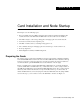
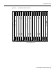
Preparing the Cards Figure 3-1 W6 Jumper W5 30549 W6 Many card sets support Y-cable redundancy. This feature requires an extra set of cards and a Y-cable. A set of commands exists to specify, delete, and display Y-cable redundancy. For instructions on setting up Y-cable redundancy, refer to the setup section for the specific card set. Note FRM and NTM front cards exist in one and two-piece versions. The two-piece card uses an ACM1. Refer to the Cisco IGX 8400 Series Reference for details.
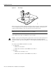
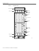
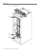
Preparing the Cards Figure 3-2 N P M A R M H8385 N P M IGX 8410 Cards, Front View General purpose card slots Note Opening the door requires a 5/32-inch Allen wrench. Cisco provides this in a combination tool (Part No. 218705). When handling the cards, wear a wrist strap to prevent damage to the cards from electrostatic discharge. The IGX 8410 cabinet has an attached wrist strap both at the front and back.
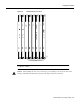
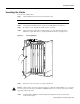
Preparing the Cards Figure 3-3 IGX 8410 Cards, Back View 8 7 6 5 4 3 2 1 H8386 ARI (recommended location) General purpose card slots SCM Blank 3-4 Cisco IGX 8400 Series Installation and Configuration
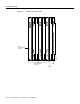
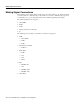
Preparing the Cards Figure 3-4 N P M IGX 8420 Card Shelf, Front View N P M A R M General purpose card slots Card Installation and Node Startup 3-5
Preparing the Cards Figure 3-5 IGX 8430 Back View Exhaust plenum Cable manager Fan tray 2 Fan power/ short cable Connector (fan 2) System power Connector (fan 1) Fan power / long Y cable Connector (fan 1) Cable manager Fan tray 1 H8347 Optional AC power tray 3-6 Cisco IGX 8400 Series Installation and Configuration
Inserting the Cards Inserting the Cards To insert a Cisco IGX module: Attach an ESD-preventive wrist strap to handle the cards. Step 1 Note The IGX 8410 cabinet has an attached wrist strap both at the front and back. Step 2 Using the 5/32-inch Allen wrench, open the Cisco IGX 8400 Series switch door. Step 3 Be sure that you are inserting the module into the correct slot.
Making Signal Connections Making Signal Connections The remaining sections of this chapter describe how to set up physical lines, ports, trunks, and signal connections. The Cisco WAN Switching Command Reference and Cisco WAN Switching SuperUser Command Reference provide important details on the commands appearing in this chapter.
Connecting Trunks Connecting Trunks The sections that follow contain basic information on how to set up the two types of trunks on the IGX node. The two trunk types are FastPacket and ATM. The supported line types are OC3/STM1, T3, E3, T1, Y1, and E1. The card sets described in this section are the network trunk module (NTM).
Setting Up a UXM-E Figure 3-7 Cable Management Cable manager Cable manager H7963 Frame bonding connection 3-10 Cisco IGX 8400 Series Installation and Configuration
Setting Up a UXM-E The following is the command sequence for bringing up the trunk. You must bring up the trunk before you add connections. For detailed command descriptions, see the command references. Step 1 To verify the correct card locations in both the local and remote nodes, enter: dspcds Step 2 Configure the cellbus bandwidth allocation for the card if you do not plan to rely on automatic increases from switch software.
Setting Up a UXM-E • The node maintains a set of retained links for the IMA trunk to keep it active. The IMA trunk does not fail unless the number of active trunks is less than the user-specified number of retained links. • The IMA trunk can provide a clock source or clock path (see cnftrk command). The first (the lowest numbered) available physical line is used. If this line fails, the next available line within the IMA provides the clock source or clock path.
Setting Up a UXM-E Removing Links from an IMA Feeder Group To remove links from an IMA group, you can use either Cisco WAN Manager or the CLI. To remove a link from an IMA group on the CLI: Step 1 Find the nodes configured as trunks connected to the IMA feeder by using the dsptrks command. Step 2 Reduce the number of retained links on the IMA feeder node. Step 3 Reduce the receive rate using the DS0 calculation on the IMA feeder node. Step 4 Repeat steps 2 and 3 on the IMA trunk.
Setting Up a UXM-E Connecting an NTM T1 or Y1 Trunk The T1 trunk connections use the NTM front card and the BC-T1 back card. Japanese Y1 connections use the NTM front card and the BC-Y1 back card. The procedure for making Y1 connections is the same as for T1 connections described below. Make the T1 connections as follows: Step 1 Bring each T1 cable through the opening at the bottom of the cabinet (if applicable) and up the back of the unit.
Setting Up a UXM-E Setting Up a UXM-E This section consists of descriptions of how to set up a port-mode UXM-E and a trunk-mode UXM-E. The descriptions consist of the steps for attaching cables and entering commands at the command line interface (CLI). For detailed information regarding the UXM-E, refer to the Cisco IGX 8400 Series Reference.
Installing Voice Cards Step 10 Configure the cellbus bandwidth allocation with cnfbusbw if you plan to activate a large number of ports on the UXM-E. Use dspbusbw or cnfbusbw to check cellbus usage and changes in bandwidth requirements for the UXM-E. For an explanation of cellbus bandwidth allocation, see the Cisco IGX 8400 Series Reference. Note Cisco recommends that you not allow oversubscription.
Installing Voice Cards Connecting a CVM to an E1 Line or a Subrate Trunk Channelized voice or data connections on an E1 line use the CVM front card and the BC-E1 back card. Subrate E1 connections use the CVM front card and the BC-SR back card. The E1 trunk interface card BC-E1 contains the E1 connector (G.703 Input/Output) that resides at the top of the back card. The BC-E1 faceplate has four, 75-ohm BNCs. Note The BC-E1 faceplate provides two connector arrangements for attaching E1 lines.
Installing Voice Cards • The total delay for a connection is defined as the sum of the propagation and trunk queuing delays. The total delay for a connection cannot be more than 25 ms different from the total delay for any other connection on the same card. The user is responsible for configuring the connections so that no difference between total delays exceeds 25 ms. If the 25 ms is exceeded, an error message is generated in the form CC0700d6, where CC is the slot number. • In System Software 8.
Installing Voice Cards Figure 3-8 Pass-Through and Standard (External) UVM T1 Cabling External UVM A. External line Passedthrough External Passing (transparent) UVM 1 UVM 2 Passedthrough External External Passedthrough Passing (transparent) UVM 1 C. Two pass-through lines UVM 2 Passing (transparent) UVM 3 H9884 B.
Installing Voice Cards Connecting a UVM to E1 Lines Voice or data connections on an E1 line use the UVM front card and the BC-UVI-2E1EC back card. The procedure for connecting the E1 lines is as follows: Step 1 Bring each cable through the opening at the bottom of the cabinet (if applicable) and up the back of the unit. You can use the cable management feature to help route the cables.
Installing Voice Cards Figure 3-9 Pass-Through and Standard (External) UVM E1 Cabling Pass-through Passedthrough Passing (transparent) UVM 1 A. One pass-through line UVM 2 B. External line UVM H9888 External The back slot line numbers correspond to the slot number in which the BC-UVI-2E1EC card resides. Record the back slot number and port number of each line. These numbers are necessary for configuring the system after you complete hardware installation.
Installing Voice Cards Connecting a UVM to J1 Lines Voice or data connections on a J1 line use the UVM front card and the BC-UVI-2J1EC back card. The procedure for connecting the J1 lines is as follows: Step 1 Bring each cable through the opening at the bottom or top of the cabinet (whatever is applicable) and along the back of the unit. You can use the cable management feature to help route the cables. Step 2 Attach each cable according to the cabling requirement (pass-through, external, and so on).
Installing Voice Cards Figure 3-10 Pass-Through and Standard (External) UVM J1 Cabling Pass-through Passedthrough Passing (transparent) UVM 1 A. One pass-through line UVM 2 B. External line UVM H9888 External The back slot line numbers correspond to the slot number in which the BC-UVI-2J1EC card resides. Record the back slot number and port number of each line. These numbers are necessary for configuring the system after you complete hardware installation.
Making Serial Data Connections Making Serial Data Connections The low-speed data module (LDM) and high-speed data module (HDM) card sets provide serial data service. Each of these front cards uses a variety of back cards. The LDM front card uses the 4-port or 8-port version of the low-speed data interface (LDI) back card for EIA/TIA-232C/D (V.24) connections. The connection ports are labeled PORT 1 through PORT 4 or PORT 1 through PORT 8. See Figure 3-11 for illustrations these back cards.
Making Serial Data Connections Configuring the Port Modes of the HDM Back Cards Small jumper boards on the back card determine whether the mode of the port is DTE or DCE. The factory-set modes of the SDI ports alternate DCE with DTE. The steps that follow describe how to change the mode of the port.
Making Serial Data Connections Figure 3-12 Changing the Mode on an SDI Card Faceplate DCE position DCE/DTE jumper board SDI 1 2 3 4 5 6 Faceplate DCE/DTE jumper board SDI 1 2 3 4 5 6 H8370 DTE position HDM and LDM Redundancy Optional redundancy for HDM and LDM cards can be provided with a second front and back card set and a Y-cable connection on each port to the customer data equipment. Note A jumper board comes with an impedance of either 100 ohms or 200 ohms.
Making Serial Data Connections Figure 3-13 Connecting a DTE or DCE Adapter Cable to an LDI LDI RS-232 cable DCE* 15-pin connector * Use DTE cable for DTE devices 25-pin connector H8357 xxxxxx xxxx xxx xxxxxx xxx xxxx x xx xx xx xx Card Installation and Node Startup 3-27
Making Frame Relay Connections Making Frame Relay Connections This section outlines how to establish Frame Relay service by setting up a universal frame module (UFM) or a Frame Relay module (FRM). The information includes details for T1, E1, HSSI, V.35, and X.25 interfaces. Detailed descriptions of the Frame Relay commands appear in the Cisco WAN Switching Command Reference.
Making Frame Relay Connections Figure 3-14 shows the Y-cable arrangement for standard cables that support one or two ports. The diagram for single-port cables applies to all back cards. The dual-port cables connect to only a V.35 or X.21 UFI. The Y-cable connects to the back card, and the standard cable runs between the access device or CPE and the base of the “Y.” Y-cable redundancy is not allowed between different line types, such as a UFI-8T1-DB-15 and a UFI-8E1-DB-15.
Making Frame Relay Connections Connecting UFM Cabling For important details on standard cables and Y-cables for the UFI back cards, refer to the cabling description in the UFM-U section of the Cisco IGX 8400 Series Reference. Take the following steps after you have inserted the cards according to the information on installing cards in the section titled “Preparing the Cards” page 1. Connect the cables as follows: Step 1 For the UFM-U/UFI card sets, make sure the cables are the correct DCE or DTE versions.
Making Frame Relay Connections Step 5 For optional Y-cable redundancy, configure the two cards by using the addyred command. For Y-cable redundancy on a HSSI card, you must use port 1 of the cards for the primary and redundant ports. For important information about Y-cable redundancy on a UFM-U, see the description in the UFM-U portion of the Cisco IGX 8400 Series Reference. Step 6 Activate the ports using the upfrport command.
Making Frame Relay Connections • FRI-X.21 has female DB-15 subminiature connectors. Cabling requirements for the Frame Relay interfaces are in Appendix C, “Cabling Summary.” Take the following steps after you have inserted the cards according to the general information on installing cards in the section “Preparing the Cards” page 1. To connect a cable: Step 1 Bring each cable through the opening at the top or bottom of the cabinet (whichever applies) and along the back of the unit.
Making Frame Relay Connections Step 2 To change to DTE, move the jumper board one row of pins away from the FRI faceplate. (See Figure 3-15.) For DTE mode, the jumper board should occupy rows 2, 3, 5, and 6. To change to DCE, plug the jumper board into the connector receptacle pin rows closest to the FRI faceplate. (See Figure 3-15.) The rows for DCE mode are 1, 2, 4, and 5. Step 3 Insert the FRI card and gently slide it in all the way to the rear of the slot.
Making Frame Relay Connections After the hardware is installed, use the addyred command to reconfigure the node to recognize the card redundancy. Refer to the Cisco WAN Switching Command Reference for more information on the commands addyred, delyred, dspyred, and ptyred. Setting Up Frame Relay Ports and Connections (FRM) This section outlines the steps for setting up and deleting Frame Relay ports, adding and configuring connections, and bundling connections.
Making Frame Relay Connections Step 10 Determine which Frame Relay class number to use when you add connections to a port. To see the parameters that a class specifies, use the dspfrcls command. To modify parameters in a class, use the cnffrcls. Step 11 Add connections to the port by using the addcon command. Enter the slot number and specify a DLCI for each end of the connection.
Making Frame Relay Connections Step 2 From a control terminal or a Cisco WAN Manager NMS workstation, to the node and enter the addalmslot command followed by the slot number where the ARM is located. This will activate the alarm reporting from the card. Step 3 Observe that the ACTIVE LED on the ARM card is on. Step 4 Testing the operation of the alarm outputs requires you to create an alarm and note the resulting alarm output.
Making External Clock Connections Table 3-2 shows the unassigned connector pins. Table 3-2 Unassigned Connector Pins Pin No.
Attaching Peripherals Attach the control terminal to the SCM. (See Figure 3-16.) Step 1 From the back of the cabinet, run the control terminal EIA/TIA-232/V.24 cable through the opening at the bottom and up to the SCM card in back slot 1. Step 2 Locate the Control Terminal connector on the SCM and attach the control terminal EIA/TIA-232/V.24 cable to it.
Attaching Peripherals LAN Connection for the Network Management Station If the network is large or extensive network statistics are needed, an Ethernet port (LAN port) should be used. Larger networks produce a greater flow of statistics data between the node and the Cisco WAN Manager workstation, so a higher speed Ethernet port is suitable. Figure 3-17 illustrates this connection.
Attaching Peripherals Configuring the LAN Port Note Configure the LAN parameters before connecting the node to a LAN. Note Refer to the Cisco WAN Manager Operations publication and the Cisco WAN Switching Command Reference publication for additional information Step 1 Contact a system administrator to obtain IP addresses for the workstation and for the IGX node.
Attaching Peripherals • GatewayIPAddr is the Internet gateway address. This is the gateway that traffic is routed through if the IGX node and workstation are on different networks. If they are on the same network, the gateway is not used. The default “none” is displayed in this case. If a gateway IP is entered and later you want to remove it, enter 192.0.0.0 opposite the prompt and “none” will again be displayed. A cnflan screen looks like this: D2.cb1 LAN superuser IGX 8410 9.3 Feb.
Attaching Peripherals Step 6 After the workstation and IGX node interface have been set up, Cisco WAN Manager can be started. After Cisco WAN Manager has started and the communication sockets are active, the dsplan screen looks like this: D2.cb1 LAN cisco IGX 8410 9.3 Feb. 27 2000 14:27 PST Active IP Address: IP Subnet Mask: TCP Service Port: Default Gateway IP Address: 192.187.207.21 255.255.255.0 5130 192.187.207.1 Maximum LAN Transmit Unit: Ethernet Address: 1500 00.55.43.00.04.
Attaching Peripherals Figure 3-18 SV+ LAN Connection via Router to an IGX Node Backbone 192.187.207.1 Router 192.187.207.11 192.187.207.21 192.187.207.200 Router AUI 192.187.210.1 SV+ 192.187.210.30 SCM H8374 Note: IP numbers are representative only. Figure 3-19 SV+ LAN Connection to an IGX Node (No Gateway) 192.187.207.200 AUI SV+ 192.187.207.30 SCM H8375 Note: IP numbers are representative only. Step 7 Switch on the control terminal (or Cisco WAN Manager workstation).
Attaching Peripherals Connecting the Printer At least one node in the network should have a printer connected. The printer connects to the AUX port on the SCM. The printer is used to print information about network operation. It can be configured to print maintenance information on a regular basis, and it can print specific diagnostic information when necessary. Instructions on using the printer for this purpose are in the Cisco WAN Switching Command Reference.
Attaching Peripherals Step 4 Tighten the EIA/TIA-232/V.24 connector screws to firmly attach the cable connector to the AUX port connector. Step 5 Plug the printer power cord into the appropriate wall receptacle. Connecting a Modem Two modems can be connected to the IGX node to provide access for remote troubleshooting and for remote alarm logging. (See Figure 3-21.) Each connection between the SCM and a modem requires a special cable and setup procedure.
Initial Startup of the IGX Connecting the Power Supply Monitor The power supply monitor (PSM) is a connector with outputs that signal an AC power supply alarm. Cisco provides no equipment that connects to the PSM connector, so user-supplied equipment is necessary. Refer to the Cisco IGX 8400 Series Reference publication for a description of the PSM outputs. Initial Startup of the IGX This section describes checkout procedures to follow after the hardware is in place and ready to receive power.
Initial Startup of the IGX Step 14 At the back of the unit, turn the circuit breakers to the ON position. In a system using a DC source, attach the cable guard (AC should already have the cable guard in place). After initial power up, DC systems can be switched off and on either at the PEM or at the building site’s resident circuit breaker.
Initial Startup of the IGX If an NPM fails the power-up diagnostic, the boot process does not finish. If this failure occurs: Step 1 Remove the failed NPM from its slot. Step 2 Install the NPM in the same slot again. Step 3 Wait for the power-up diagnostic to run. Step 4 If the NPM fails the power-up diagnostics again, replace it with a known-good NPM. For card replacement procedures, refer to Chapter 4, “Troubleshooting”.
IGX Configuration Summary • If a power supply AC Okay LED or DC Okay LED is off, try removing and inserting the power supply. If any LED remains off, see Chapter 4, “Troubleshooting”. Checking the Power Supplies (AC Systems) The means for verifying the correct power supply voltages are the DC Okay and AC Okay LEDs on each power supply. If either of these LEDs is off, a problem exists in relation to that supply. Power supplies are not field-adjustable.
IGX Configuration Summary — Set up any subrate trunk interface control templates if desired (cnftrkict). • For setting up voice lines: — Activate the line (upcln or upln). — Configure the line (cnfln). If you use cnfln to configure the line for voice SVC caching in conjunction with VNS, see to the VNS documentation for a description of this service and the CVM or UVM description in the Cisco IGX 8400 Series Reference for line-information. — Configure redundancy (addyred).
IGX Configuration Summary • For setting up data connections: — Add the connections (addcon). — Configure connection parameters (cnfdclk, cnfcldir, cnfict). • For setting up Frame Relay connections: — Add the connections (addcon). — Configure connection classes (cnfcls). — Configure control templates, channel utilization, and channel priorities (cnfict, cnfchutl, cnfchpri).
IGX Configuration Summary Figure 3-22 illustrates the sequence of using addshelf either locally or remotely to add one or more interface shelves. To delete an interface shelf, use delshelf after you delete connections and the active interfaces. To view status of an interface shelf, execute dspnode at the routing hub. (The dspnw command shows an alarm on a node but does not specify an interface shelf.