This document is exclusive property of Cisco Systems, Inc. Permission is granted to print and copy this document for noncommercial distribution and exclusive use by instructors in the IP Telephony course as part of an official Cisco Networking Academy Program.
Lab 2.1.1a Basic Setup for the CME Router with Switch Module Objectives • Configure a Cisco router in preparation for CallManager Express (CME) • Configure a switch in preparation for CME Equipment Requirements • Cisco CallManager Express (CME) capable router with switch module • Workstation with an Ethernet 10/100 NIC installed • Two Cisco IP phones In this lab, the ACME.com Company has decided to deploy CallManager Express in the enterprise.
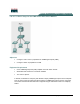
Step 1 Assign a Pod Number a. Ask the instructor to assign a pod number to the lab group. What pod number was the group assigned? ____________________ Step 2 Erasing Configuration and VLANs from the Router a. The router with a four port switch module stores VLAN information in Flash memory. To ensure the router does not have a previous configuration, connect a console cable to the router and power on the router. b.
g. Create two VLANs—one for the voice VLAN and one for the data VLAN. VLAN 1, the management VLAN, is already created. Note that the X shown in the command is the pod number. CMERouterX# vlan database CMERouterX(vlan)# vlan X0 name Data state active CMERouterX(vlan)# vlan X5 name Voice state active h. Go into the configuration mode for the management VLAN by entering global configuration mode and typing the command interface vlan 1.
Step 4 Configure the Router Switch Ports a. Verify the slot into which the router switch four port module inserts by (1) viewing the router and (2) using the show diag command. Look for the words 4 Port FE Switch. CMERouterX# show diag b. Based on the previous step, into what slot does the switch module insert? _________________ c. Use the show ip interface brief command to verify the slot and the format used for the interface.
c. From privileged mode verify the port is properly configured as a trunk port by using the show interfaces slot/port-adapter/port switchport command (where interface-id is the switch port used to connect to the router). CMERouterX# show interfaces fastethernet slot/port-adapter/port switchport d. What is the status of the switch port (shown as switchport in the command output)? _____________________________________________________________________________ e.
Step 6 Save the Router Configuration a. Save the router configuration by typing the following command: CMERouterX# copy running-config startup-config Note: Save the router configuration to a text file as well. These configurations will be required in future labs. 7 - 165 IP Telephony v1.0 Lab 2.1.1a Copyright © 2005, Cisco Systems, Inc.
Answers to 2.1.1a lab 1a. The pod number depends on what the instructor assigned. 3m. 10.X0.0.1 (Pod1 is 10.1.0.1; Pod2 is 10.2.0.1, etc.) 4b. Depends on the router being used 4d. Usually this answer will be something similar to the following: FastEthernet 0/0/0, 0/0/1, 0/0/2, and 0/0/3 OR FastEthernet 1/0/0, 1/0/1, 1/0/2, and 1/0/3. 4f. DOT1Q is the parameter that specifies the IEEE 802.1Q trunking protocol to be used on the subinterface. The 802.
Lab 2.1.1b Basic Setup for the CME Router and Switch Objectives • Configure a Cisco router in preparation for CallManager Express (CME) • Identify the DHCP configuration commands • Configure a switch in preparation for CME Equipment Requirements • Cisco CallManager Express (CME) capable router • Inline Power capable switch or non-inline power switch with power injectors • Workstation with an Ethernet 10/100 NIC installed In this lab, the ACME.
Step 2 Basic CME Router Configuration a. Connect to the console port of a Cisco CallManager Express router and power it on. If the router has a configuration already on it, erase the router and reload it. b. Enter privilege mode, and then configuration mode. c. Change the hostname of the router. Use the command hostname CMERouterX, where X is the pod number assigned to the group. Throughout the rest of the lab, use IP Telephony Table 1 parameters based on the pod number assigned.
j. Configure the management VLAN subinterface with an IP address appropriate for the management VLAN. From the subinterface configuration mode, enter the IP address for the management VLAN based on the information found in IP Telephony Table 1. Use the command ip address 10.X.0.1 255.255.255.0 command (where X is the pod number). CMERouterX(config-subif)# ip address 10.X.0.1 255.255.255.
r. Configure the EIGRP routing protocol by using the router eigrp 100 command to start an EIGRP process with an autonomous system number of 100. Then enter the command network 10.0.0.0, which enables and advertises EIGRP updates on all 10.0.0.0-configured interfaces. CMERouterX(config)# router eigrp 100 CMERouterX (config-router)# network 10.0.0.0 s. Connect a straight-through cable between the Ethernet port on the router and port 1 on the switch. t.
Step 5 Assign a name to the switch a. Enter privilege mode and then configuration mode. Use the hostname CMESwitchX command (where X is the pod number) to name the switch. Throughout the rest of the lab, use IP Telephony Table 1 parameters based on the pod number assigned. Switch# configure terminal Switch(config)# hostname CMESwitchX Step 6 Examine the current running configuration a.
c. Set the default gateway for the switch to 10.X.0.1 (where X is the pod number). CMESwitchX(config)# ip default-gateway 10.X.0.1 d. What is the purpose of putting a default gateway on a switch? (Be specific.) __________________________________________________________________ __________________________________________________________________ Step 10 Verify and activate the management VLANs settings a. Verify the interface settings on VLAN 1 as follows: CMESwitchX# show interfaces vlan 1 b.
e. Besides trunking, what are the other modes for which a switch port can be configured? _____________________________________________________________________________ f. From enable mode verify the port is properly configured as a trunk port by using the show interface interface-id switchport command (where interface-id is the switch port used to connect to the router). CMESwitchX# show interfaces fastethernet 0/1 switchport g.
Step 14 Create VLANs on the switch a. Manually create the data and voice VLANs in the VLAN database. The X in the VLAN number is the pod number. CMESwitchX# vlan database CMESwitchX(vlan)# vlan X0 CMESwitchX(vlan)# vlan X5 CMESwitchX(vlan)# exit Step 15 Configure switch ports for IP phones a. Cable the two IP phones to switch ports 4 and 6 using straight-through cables. b. Configure the two IP phone ports to use the IEEE 802.1Q trunking protocol using the switchport trunk encapsulation dot1q command.
f. Save the switch configuration by typing the following command: CMESwitchX# copy running-config startup-config Note: Save the router and switch configurations to a text file as well. These configurations will be required in future labs. 17 - 165 IP Telephony v1.0 Lab 2.1.1b Copyright © 2005, Cisco Systems, Inc.
Answers to 2.1.1b lab 1a. The pod number depends on what the instructor assigned. 2h. The interfaces on the router depends on the router model and physical configuration being used by the student. 2j. 10.X.0.1 (Pod1 is 10.1.0.1; Pod2 is 10.2.0.1, etc.) 2l. DOT1Q is the parameter that specifies the IEEE 802.1Q trunking protocol to be used on the subinterface. The 802.1Q trunking protocol is the most commonly used trunking protocol. The alternative is ISL.
12k. all of the VLANs 12m. If this command can be done, it is the port that the student is using to connect to the router, port 1. 12n. VLAN X0 (where X is the pod number) 12o. 1-4094 (all of them) 12p. VLAN 1 13b. Yes 19 - 165 IP Telephony v1.0 Lab 2.1.1b Copyright © 2005, Cisco Systems, Inc.
Lab 2.1.2 Installing Cisco CME Software Objective • Install Cisco CallManager Express (CME) software on the router Equipment Requirements • Cisco CallManager Express (CME) capable router • Cisco router IOS version that supports CallManager Express • Workstation with Ethernet 0/100 NIC installed • TFTP server application • Access to Table 1 IP Telephony IP Addressing Scheme and VLAN Assignment document In this lab the ACME.
Step 1 Configure the TFTP server Note: If the router has multiple Ethernet interfaces use the lowest numbered interface. For example, if there are two Ethernet interface, 0 and 1, then 0 should be used. a. Ensure the computer that has the TFTP server application loaded on it is connected to the Ethernet port of the router. Be sure that the computer has an appropriate IP address and default gateway assigned. See the IP Telephony Table 1 for IP addressing assignment. An example IP address is 10.1.0.
c. Use the show flash command to verify that the IOS file is present in flash memory. CMERouterX# show flash For example: -#- --length-- -----date/time------ path 1 24119024 Mar 24 2005 22:17:00 +00:00 c2800nm-ipvoice-mz.12311.T3.bin 32143304 bytes available (24119024 bytes used) d.
Answers to 2.1.2 lab 1e. Student’s choice for IP address. 2b. Yes 2f. Yes 23 - 165 IP Telephony v1.0 Lab 2.1.2 Copyright © 2005, Cisco Systems, Inc.
Lab 2.1.3 Connecting the IP Phone to a Switch Objective • Connect an IP phone to a switch and provide power to it Equipment Requirements • Inline power capable switch or non-inline power switch with power injectors • Two Cisco IP phones This lab relies on labs 2.1.1 being successfully completed and loaded. In this lab the ACME.com Company wishes to implement IP telephony. In order to do so, the phones must receive power in order to work.
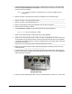
Step 1 Understanding the two types of switches a. There are two types of switches that can be used with Cisco IP phones: (1) an inline power switch and (2) a non-inline power switch. A switch that can provide power to another device such as an IP phone has the words INLINE POWER stenciled on it as shown below. A non-inline power switch does not have the words INLINE POWER stenciled on it. An example of this type of switch is the 2950.
d. Connect a straight-through Ethernet cable from the 10/100 SW port on the IP phone to any 100 MB port on the inline power switch. e. What indication is shown that the phone is receiving power? _________________________ __________________________________________________________________________ Step 3 Cabling the IP phone to a non-inline power switch a. Connect power to the non-inline power switch. b. In order to connect a Cisco IP phone to a non-inline power switch, a power injector is needed.
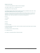
The port on the left labeled 10/100BaseTX to Device is used to connect to the IP phone (via a straight-through cable).The port on the right labeled 10/100BaseTX to Network is used to connect to a non-inline power switch such as a 2950 switch (via a straight-through cable). c. Connect a straight-through cable from the left power injector port labeled 10/100BaseTX To Device to the IP phone port labeled 10/100 SW. d.
Answers to 2.1.3 Lab 1b. At the time this lab was written, the 2970 was the most powerful 29xx series switch and it does not support inline power for all of its ports. 2b. 10/100 SW and 10/100 PC 2e. The phone starts displaying words on the screen. Also, when power is first applied, the buttons on the bottom start lighting up sequentially. 3f. The phone starts displaying words on the screen. Also, when power is first applied, the buttons on the bottom start lighting up sequentially.
Lab 2.1.4 Resetting a 7900 Series Cisco IP Phone to Factory Defaults Objective • Erase the current configuration from an IP phone Equipment Requirements • Cisco IP Phone 79xx series • Inline power capable switch or non-inline power switch with power injectors In this lab, the ACME.com Company has decided to deploy CallManager Express (CME) in the enterprise. First, the IP phones must be reset. They were used in a test lab by the network support staff and currently have various configurations.
d. What is an advantage of using an in-line power switch? ________________________________ _____________________________________________________________________________ Step 2 Reset the Cisco IP phone a. On the IP phone press the following keys to unlock the Network Configuration menu: **#. Note: No feedback will be given on the screen. b. Press the Settings button on the phone. If the phone buttons are unlabelled, it is the button that has a checkmark on the button. c.
Answers to 2.1.4 lab 1c. Depends on the equipment available in the classroom. 1d. An inline power switch can provide power to remote devices such as an IP phone through an Ethernet cable. This saves power outlet in the office where the remote device is located. 2d. Depends on the IP phone being used. 2g. All Fields Saved 2j. All Changes Saved 31 - 165 IP Telephony v1.0 Lab 2.1.4 Copyright © 2005, Cisco Systems, Inc.
Lab 3.1.
Step 1 Configure Cisco IP Telephony Express using the Automated Method a. From privilege exec (EXEC) mode on the router, use the show running-config command and view the current configuration. Save or print a copy of the current configuration to compare with changes later in this lab. CMERouterX# show running-config b.
o. Refer to the Table 2 IP Telephony Dial Plan (back of lab manual) to find the appropriate first extension number. Use the first column in the table to locate the pod being used. The second column lists extension numbers. From the second column pick the first number in the range listed for the pod being used. For example, if Pod 1 is being used then the first extension number is 5000. p. When asked if DID (Direct-Inward-Dialing) is used, answer y, and press Enter.
Step 3 Review Changes to the Running Configuration a. From privilege exec (EXEC) mode, enter the show running-config command and view the changes made in the configuration. Pay particular attention to the telephony-service section. Compare this configuration with the configuration saved prior to this lab. CMERouterX# show running-config b. Write the commands that changed, and the commands that were created as a result of the automatic telephony-service configuration utility used in this lab.
Step 5 Reload Router a. Do NOT save the router configuration. However, it is recommended that you copy the current configuration to a text file that can be used later. b. Reload the router so that a manual configuration can be completed in the next task. Do NOT save the changes. 36 - 165 IP Telephony v1.0 Lab 3.1.1 Copyright © 2005, Cisco Systems, Inc.
Answers to 3.1.1 lab 1d. Student dependent 1q. Pod dependent 1s. Pod dependent 3b. ip dhcp pool ITS network 10.15.0.0 255.255.255.0 option 150 ip 10.15.0.1 default-router 10.15.0.1 ! tftp-server flash:P00303020214.bin (perhaps) ! telephony-service load 7960-7940 P00303020214 (perhaps) max-ephones 4 max-dn 4 ip source-address 10.15.0.1 port 2000 auto assign 1 to 4 create cnf-files version-stamp Jan 01 2002 00:00:00 dialplan-pattern 1 5105555...
call-forward busy 6001 call-forward noan 6001 timeout 18 ! ephone-dn 4 dual-line number 5003 call-forward busy 6001 call-forward noan 6001 timeout 18 ! ephone 1 mac-address 0013.C43B.4999 type 7940 button 1:1 ! ephone 2 mac-address 000A.B7B1.33F5 type 7960 button 1:2 ! ephone 3 ! ephone 4 4f. Yes. The PC’s IP address should probably be 10.X0.0.11. 38 - 165 IP Telephony v1.0 Lab 3.1.1 Copyright © 2005, Cisco Systems, Inc.
Lab 3.1.2 CME Manual Phone Setup Objective • Configure IP Phones using the manual configuration process Equipment Requirements • Cisco CallManager Express (CME) capable router with specific files for IP phone (basic CME .tar file) • Inline power capable switch or non-inline power switch with power injectors • Workstation with an Ethernet 10/100 NIC installed • One Cisco IP phone In this lab the ACME.
Step 1 Verify if the Telephony Service is Running a. If necessary, put the basic configuration from 3.1.1 on the router and switch. b. Ensure that NO phones are connected to the switch at this time. c. Access the Cisco CallManager Express router and use the show running-config | begin tele command to verify that the telephony service has not been configured.
Note: The .tar file must match the IOS version on the CME router. The file must be extracted and uploaded to the router Flash memory from a TFTP server. Copy the .tar file into the appropriate TFTP server folder. From privileged mode, use the archive tar /xtract tftp://tftp_server_ip_address/.tar_filename flash:. An example of this command is as follows: archive tar /xtract tftp://10.3.0.33/cme-basic-123-11T.tar flash:.
CMERouterX(config-telephony)# max-dn ? _________________________________________________________________ g. Use the max-dn command to configure the maximum number of directory numbers to 20, as this will be sufficient for the classroom lab. CMERouterX(config-telephony)# max-dn 20 h. The load command updates the Cisco IOS Telephony Services (Cisco ITS) configuration file for a specific type of IP phone to add the name of the correct firmware file that the phone should load.
j. Use the create cnf-files command to build XML configuration files that will be used by the phones during the boot process. CMERouterX(config-telephony)# create cnf-files k. What message(s) did the router display when the create cnf-files command was entered? _________________________________________________________________________ _________________________________________________________________________ l.
r. Add an ephone-dn for the first line appearance on the first phone in the pod by entering the ephone-dn 1 dual-line command. The dual-line parameter defines the type of ephone-dn is being created. CMERouterX(config)# ephone-dn 1 dual-line In ephone-dn mode enter the number X000 command (where X is the pod number). CMERouterX(config-ephone-dn)# number X000 s. Enter a name that will be associated with this DN by entering the name firstname lastname command. Either make up a name or use a student’s name.
w. The button command is used to define properties to the buttons located to the right of the IP phone’s LCD. The button command has a number that follows it with the number 1 representing the top button on the IP phone. The number is followed by a separator character that specifies phone characteristics. For example, the colon separator assigns the phone a normal ring, a single pulse for internal calls and a double pulse for external calls.
Answers to 3.1.2 lab 3b. Answers will vary according to IOS version, but common answers will be similar to the following: P00303020214.bin and P00305000301.bin. 4d. 52 (2821 with 12.3.11T); 30 (1760 with 12.3(8)T3. Note that this may vary according to router model and IOS version. 4f. 192 (2821 with 12.3.11T); 150 (1760 with 12.3(8)T3. Note that this may vary according to router model and IOS version. 4h.
Lab 3.1.3 CME Partially Automated Phone Setup Objective • Configure an IP phone using the partially automated process Equipment Requirements • Cisco CallManager Express (CME) capable router with .tar configuration files already extracted • Inline power capable switch or non-inline power switch with power injectors • Workstation with an Ethernet 10/100 NIC installed • Two Cisco IP Phones (one of which was configured in Lab 3.1.2 lab) In this lab the ACME.
Step 1 Add a Second IP Phone by using the Auto Assign Method a. Ensure the second IP phone is not connected to the switch. Add a second ephone-dn by using the ephone-dn 2 dual-line command. CMERouterX(config)# ephone-dn 2 dual-line b. Use the number X001 command to add a DN (where X is the pod number). CMERouterX(config-ephone-dn)# number X001 c. Enter telephony service mode by entering the telephony-service command from global configuration mode. CMERouterX(config)# telephony-service d.
j. Lift the handset of the first IP phone and dial the other IP phone by pressing the four digit identifier of the second phone. This number is located in the upper right display of the second phone. k. If the second IP phone rings, save your configuration by using the copy running-config startup-config. If unsuccessful, troubleshoot as necessary. 49 - 165 IP Telephony v1.0 Lab 3.1.3 Copyright © 2005, Cisco Systems, Inc.
Answers to 3.1.3 lab 1e. IOS dependent, but a common answer is 12. 2c. The message that appears is IOS dependent, but an example of the message is as follows: %IPPHONE-6-REGISTER: ephone-2:SEP000D2890D043 IP:10.15.0.12. The important thing to remember is that the message states that a particular phone has registered. 2e. Each ephone lists a section that has the word REGISTERED at the end of the line. 2g. An annoying, repeating tone that sounds like any phone when a number has not been dialed. 2h.
Lab 4.1.1 Configuring a FXS Port Objective • Configure a router FXS port for an analog phone Equipment Requirements • Cisco CallManager Express (CME) capable router with a FXS port • Inline power capable switch or non-inline power switch with power injectors • One analog phone with RJ-11 cable • One IP phone In this lab the ACME.com Company wants to be able to reuse an analog phone for emergency calls. The analog phone plugs into the router FXS port.
Step 1 Verify FXS interface a. Power on the router and switch. b. Connect the IP phones. Test them by calling from one phone to another. c. Use the show hardware privileged mode command to verify a FXS interface is installed in a router. d. How many FXS interfaces are installed based on the command output? ___________________ e. Look at the router and notice how the slots where WICs are installed are numbered. On a 2800 series router the slots are numbered to the side of the cards.
b. Access global configuration mode on the router and configure the FXS port for connectivity. The first step is to configure a dial-peer for POTS connectivity. CMERouterX(config)# dial-peer voice 1 pots c. The destination-pattern number command defines the phone number that can be used to reach the analog phone. Use Table 2 Router FXS Port 0 column to locate a number that corresponds to the appropriate pod. (For example, Pod 3 would use the command: destinationpattern 5555088.
Answers to Lab 4.1.1 1d. The answer is router dependent, but the common answer is 2. 1f. The answer is router dependent. 1h. The answer is router model dependent. 1j. Dormant 1k. Up 1m. No. 2g. Pod dependent: Pod 1 5555028; Pod 2 5555058; Pod 3 5555088; Pod 4 5555128 2i. Yes 54 - 165 IP Telephony v1.0 Lab 4.1.1 Copyright © 2005, Cisco Systems, Inc.
Lab 4.1.2 Configuring a FXO Port Objective • Configure a router FXO port for an analog phone Equipment Requirements • Cisco CallManager Express (CME) capable router with a FXO port • Inline power capable switch or non-inline power switch with power injectors • Adtran • Two IP phones • Two analog phones This lab relies on labs 2.1.1, 2.1.2, 3.1.1, and 4.1.1 being successfully completed and loaded. In this lab the ACME.
Step 1 Configure the FXO Port a. Connect a RJ-11 phone cable from the lowest numbered FXO port on the router to a port on the Adtran Octal FXS card. b. What port on the Adtran was used to connect the FX0 router port? _______________________ c. What slot does the FXO card use on the router? ______________________________________ d. Use the show running-config | begin voice-p command to verify the slot number and the format of the slot number. e.
f. From the analog phone attached to router FXS port, dial the number associated with the analog phone attached to the Adtran. The phone numbers used on the Adtran Octal FXS ports are as follows: port 1 phone number is 555-6001; port 2 is 555-6002; port 3 is 555-6003, etc. The analog phone connected directly to the Adtran port should ring. g. Does the called analog phone ring? If not, perform appropriate troubleshooting before proceeding. ____________ h.
Answers to Lab 4.1.2 1b. Student’s choice 1e. Router model dependent. An example on a 2811 router is 0/2/0. 2g. Yes 2i. List of Matched Outgoing Dial-peer(s): 1: Dial-peer Tag=5 2l. Yes 58 - 165 IP Telephony v1.0 Lab 4.1.2 Copyright © 2005, Cisco Systems, Inc.
Lab 4.1.3 Configuring PRI Interface and DID Objective • Configure a router POTS and PRI interface Equipment Requirements • Cisco CallManager Express (CME) capable router with a T1 PRI port • Inline power capable switch or non-inline power switch with power injectors • Two IP phones • Two analog phones • Adtran • Special T1 cable 59 - 165 IP Telephony v1.0 Lab 4.1.3 Copyright © 2005, Cisco Systems, Inc.
This lab relies on labs 2.1.1, 2.1.2, 3.1.1, and 4.1.1, being successfully completed and loaded. In this lab the ACME.com Company has decided that the analog connection to the PSTN is not sufficient and, as a result, a PRI will be added to give additional capacity and to add DID capability. The analog connection will be kept for a secondary connection to the PSTN. Configure the PRI with the following settings. Note: This lab uses the Adtran for simulating a PBX.
Step 2 Configure the ISDN Switch Type a. From global configuration mode, use the command isdn switch-type primary-ni to set the PRI switch type. Note that this type must be the same one being used by the provider. In this lab, the provider is the Adtran unit, and it has been configured with the primary-ni ISDN switch type. CMERouterX(config)# isdn switch-type primary-ni b.
j. Use the command show isdn status and verify that Layer 1 is ACTIVE, and that Layer 2 shows MULTIPLE_FRAME_ESTABLISHED. CMERouterX# show isdn status k. Did the show isdn status command output show the proper states (ACTIVE and MULTIPLE_FRAME_ESTABLISHED)? If not, perform appropriate troubleshooting. __________ l. In the show isdn status output notice on the second line of the output that a serial port is listed. m. Write the serial interface port number as this number is shown in the command output.
pattern. For example, the command destination-pattern 555[4,6]… directs the router to send a call starting with 5554XXX or 5556XXX out the specified port. The numbers in the brackets mean either a 4 or a 6. The three periods represent any number 0-9. This step uses this command syntax to allow any number starting with 5554 or 5556 to send out the port designated in the next step. CMERouterX(config-dial-peer)# destination-pattern 555[4,6]… h.
f. Use the port X/X/X:23 command to apply the dial peer to a specific interface. This command allows calls that come in from the previously defined numbers (5555xxx) to be allowed through a particular router port. An example of this command is as follows: port 1/0/0:23 or port 1/0:23 (depending on what model of NM-HDV2-1T1/E1 is being used). Use the port parameters previously documented in a question. CMERouterX(config-dial-peer)# port X/X/X:23 g.
Answers to Lab 4.1.3 1b. Hardware dependent, but the module is normally inserted into slot 1. 1d. Yes and how it lists is router dependent. An example is controller T1 1/0/0 2b. Other types include the following: primary-4ess, primary-5ess, primary-des100, primary-net5, primary-ntt, primary-qsig, primary-ts014 3d. Router model dependent, but the normal answer will be 1. 3k. Yes 4d. The router does not know where to send the call.
Lab 4.1.4 Configuring VoIP Dial-Peers Across a WAN Link Objective • Configure the VoIP dial peers across a WAN link. Equipment Requirements • Two Cisco CallManager Express (CME) capable routers with a serial port • Two inline power capable switch or non-inline power switch with power injectors • Adtran • Two IP phones • Two analog phones This lab relies on labs 2.1.1, 2.1.2, and 3.1.1 being successfully completed and loaded. In this lab the ACME.
Step 1 Configure the Serial Interface a. In this lab, Pod 1 and Pod 2 will partner, and Pod 3 and Pod 4 will partner. b. Ensure that a serial cable connects from the lowest serial interface on the lowest pod number router terminating on the other pod’s lowest number router serial interface. c. On both pods, use the show ip interface brief command to verify that (1) a serial interface is installed and (2) the lowest numbered serial interface. d.
b. Associate a pattern to the dial peer by using the global configuration mode command destination-pattern digits. Refer to Table 2 for the destination patterns being used. Depending on the pod number, use one of the following commands to configure a destination pattern. Note that the period(s) at the end of the command is part of the command. Pod 1- destination-pattern 50[3,4,5]. Pod 2- destination-pattern 50[0,1,2]. Pod 3- destination-pattern 51[0,1,].. Pod 4- destination-pattern 50[6,7,8].
b. The G729 codec uses an 8kbps data rate. Reconfigure the codec to use the G729 codec by entering the command codec g729br8. CMERouterX(config-dial-peer)# codec g729br8 c. Coordinate with the partner pod to place two simultaneous calls across the WAN link by dialing the four digit extensions. d. How is the voice quality? Remain connected.
Answers to Lab 4.1.4 1d. Hardware dependent, but common answers include serial 0/0 or serial 0/1/0. 1m. No the call did not complete because a dial peer has not been defined. 1n. Unknown number is the message that displays. 3b. Voice quality is tolerable. There is a delay. 3c. Yes. 3e. The quality is worse with the second call. 3g. TxType:G711u is the indication shown on the type of codec being used. 4d. Voice quality is OK, but less quality than the first call with the G711 codec.
Lab 4.1.5 Configuring Class of Restriction Objective • Configure Class of Service on the IP telephony network. Equipment Requirements • Two Cisco CallManager Express (CME) capable routers with a serial and PRI ports • Two inline power capable switch or non-inline power switch with power injectors • Adtran • Two IP phones • Two analog phones This lab relies on labs 2.1.1, 2.1.2, 3.1.1, 4.1.1, 4.1.3, and 4.1.4 being successfully completed and loaded. In this lab ACME.
• Configure the lowest numbered IP phone to be able to call over the WAN, but not over the PSTN • Configure the highest numbered IP phone to be able to call to any destination that the router can call • The analog phone should be able to call across the WAN or the analog PSTN • The digital PSTN should not be available to the analog phone Step 1 Configure Class of Restriction a. In this lab do NOT save the changes made to the router.
m. Type exit to go to global configuration mode. Define a COR list by using the command dial-peer cor list Type1. CMERouterX(config)# dial-peer cor list Type1 n. Put a member in the COR list with the command member WAN. CMERouterX(config-dp-corlist)# member WAN o. Type exit to go to global configuration mode. Define a COR list by using the command dial-peer cor list Type2. CMERouterX(config)# dial-peer cor list Type2 p. Put the first of two members in the COR list with the command member WAN.
i. In ephone-dn mode, enter the command cor incoming Type1. CMERouterX(config-ephone-dn)# cor incoming Type1 j. Type exit to go to global configuration mode. Enter dial-peer voice 1 pots to enter dial peer configuration mode. CMERouterX(config)# dial-peer voice 1 pots k. Assign an outbound COR list to the dial peer with the command cor incoming Type2. CMERouterX(config-dial-peer)# cor incoming Type2 l.
Answers to 4.1.5 lab 2c. Student’s opinion 2m. Yes 75 - 165 IP Telephony v1.0 Lab 4.1.5 Copyright © 2005, Cisco Systems, Inc.
Lab 5.1.1 Configure GUI for System Administrator Objective • Configure and use the GUI system administrator interface Equipment Requirements • Cisco CallManager Express (CME) capable router • Appropriate .tar file loaded on the router or available from the instructor or student assistant • Inline power capable switch or non-inline power switch with power injectors • Workstation with an Ethernet 10/100 NIC installed • Two Cisco IP phones • TFTP Server application This lab relies on labs 2.1.
• Enable the GUI on the CallManager Express router using files located on the TFTP server • Create a username and password • Use the GUI to create an ephone-dn and assign it to one of the two IP phones • Use the GUI to add a speed dial to one of the two IP phones • Use the GUI to change the date and time format on the IP phones • Use the GUI to change the system time Step 1 Configure the GUI interface for the System Administrator a.
extracting ephone_admin.html (6146 bytes)! extracting logohome.gif (4658 bytes)! extracting normal_user.html (3724 bytes)! extracting normal_user.js (76732 bytes)!!!!!!!!!!!!!!! extracting sxiconad.gif (843 bytes)! extracting telephony_service.html (2357 bytes) extracting uparrow.gif (870 bytes)! extracting xml-test.html (9968 bytes)!! extracting xml.template (3311 bytes)! [OK - 788992 bytes] d. Was the extraction successful? If not, troubleshoot as necessary.
Step 3 Configure a speed dial using the GUI a. Ensure the PC that will be used to access the CME GUI either (1) connects to a switch port that has been configured for the data VLAN or (2) connects to the 10/100 PC port on one of the IP phones. The PC can be configured for DHCP and if so configured, should receive an IP address from the CME router. Ensure the router has been configured for a data DHCP pool (see previous lab).
o. What feedback is received as a result of clicking the OK button? _______________________ p. In the message that appears on the screen, click the OK button to clear the message. q. Look at the IP phone that was being changed. What happens as a result of creating a speed dial using the GUI? ________________________________________________________________ r. Once the phone has reset, what has changed on the phone display? _____________________________________________________________________________ s.
Answers to 5.1.1 Lab 1b. Yes 1d. Yes 3c. Student dependent, but it should be 10.X0.0.X (where the first X is the pod number and the second X is a number other than 1 or 4—these are used by the router and the switch). 3e. No, the student could not log in because the web admin system command was used to define the username and password needed to access CallManager Express through a web page. 3g. Configure, Voice Mail, Administration, Reports, and Help 3i.
Lab 5.1.2 Configure GUI for Customer Administrator Objective • Configure and use the GUI interface for the customer administrator Equipment Requirements • Cisco CallManager Express (CME) capable router • Inline power capable switch or non-inline power switch with power injectors • Workstation with an Ethernet 10/100 NIC installed • Two Cisco IP phones • TFTP server application This lab relies on labs 2.1.1, 2.1.2, 3.1.1, and 5.1.1 being successfully completed and loaded. In this lab ACME.
• Create credentials of ACMEcust with a password of cisco • Copy the XML file using a TFTP server • Examine the context of the XML file Step 1 Configure a Phone using the GUI interface for the Customer Administrator a. Ensure the phones can connect to one another. If they cannot, redo previous labs. b. Use the show running-config | begin tele command to view part of the current configuration. CMERouterX# show running-config | begin tele c.
f. When prompted for a username and password, use the System Administrator account (ACMEadmin for the username and cisco for the password). g. How many System Parameters can be changed using the System Administrator account? _____ h. Note that the Customer Administrator and the System Administrator have the same level of access. Logout of the CallManager GUI by clicking on the Logout link in the upper right corner. Step 4 Download XML Template a. Return to the router CLI. b.
Answers to Lab 5.1.2 2c. The following line has been added: web admin customer name ACMEcust password cisco 3c. 17 in 12.3.11T and 16 in 12.3(8)T3 IOS version. Other IOS versions may be different. 3g. 17 in 12.3.11T and 16 in 12.3(8)T3 IOS version. Other IOS versions may be different. 4d. Yes 4f. The following message appears as the transfer occurs and completes successfully: !! 3311 bytes copied in 0.036 secs (91972 bytes/sec) 4h. Presentation 85 - 165 IP Telephony v1.0 Lab 5.1.
Lab 5.1.3 Configure GUI for Phone User Objective • Configure and use the GUI for the Phone User Equipment Requirements • Cisco CallManager Express (CME) capable router • Inline power capable switch or non-inline power switch with power injectors • Workstation with an Ethernet 10/100 NIC installed • Two Cisco IP phones This lab relies on labs 2.1.1, 2.1.2, 3.1.1, 5.1.1, and 5.1.2 being successfully completed and loaded. In this lab the ACME.
• Configure a user named KHampton and a password of cisco for the IP phone with a sequence number of 2 from the CLI • Open the GUI and log in as one of the user accounts created Step 1 Configure a Phone using the GUI for the Phone User a. Use the show running-config | begin ephone command to view part of the current configuration. CMERouterX# show running-config | begin ephone b. Open the Web browser on the student PC and enter the URL of http://10.X0.0.1/ccme.html (where X is the pod number).
m. Save the router changes. CMERouterX# copy running-config startup-config n. Open a Web browser and use the URL http://10.X0.0.1/ccme.html (where X is the pod number). Authenticate with the EFriend account and a password of cisco. o. Point to the Configure menu option. p. What is different from the other Web accounts? ______________________________________ q. Click on the Phone option (under Configure). r. Does the system allow any phone except for ephone1 to be configured? ___________________ s.
Answers to 5.1.3 Lab 1e. Non Exempt is the default value. 1j. Answers will vary depending on the type of phone configured, but an example is listed below: ephone 1 username "EFriend" password cisco Based on what we did in this lab at this point the only new line in the configuration is username “EFriend” password cisco. 1p. The only option is Phone. The other options of Extensions and System Parameters are not available. 1r. No 89 - 165 IP Telephony v1.0 Lab 5.1.3 Copyright © 2005, Cisco Systems, Inc.
Lab 5.1.4 Configuring Call Transfer and Call Forward Objective • Transfer calls and set up call forwarding Equipment Requirements • Cisco CallManager Express (CME) capable router • Inline power capable switch or non-inline power switch with power injectors • Workstation with an Ethernet 10/100 NIC installed • Two Cisco IP phones • One analog phone This lab relies on labs 2.1.1, 2.1.2, 3.1.1, 4.1.1, 5.1.1, and 5.1.2 being successfully completed and loaded. In this lab the ACME.
• Configure consultative transfer • Use the IP phone to configure call forward to the other IP phone • Restrict the ability to forward calls from the IP phone using IOS commands Step 1 Configure Call Transfer and Call Forward a. Check connectivity between the analog phone and one of the IP phones. From the analog phone, dial one of the IP phones. b. Does the phone connection work between the analog phone and the IP phone? If not, troubleshoot as necessary.
k. What message appears when all calls have been forwarded to another IP phone? ____________________________________________________________________________ l. From the analog phone, call the number of the second IP phone. The call should be forwarded to the first IP phone. m. Does the first IP phone ring? If not, troubleshoot as necessary. ________________ n. Press the CFwdAll softkey button on the second IP phone to disable the call forwarding. Step 2 Examining Call Forward Features a.
Answers to 5.1.4 Lab 1b. Yes 1d. Yes 1e. Student’s own reasoning, but blind transfer is that the phone where the call is being transferred to cannot tell the phone number that transferred the call. Only the originating number shows. Some companies would want to know the person doing the transferring of the call (administrative assistant versus the general switchboard). 1k. Forwarded to X000 (where X is the pod number) 1m. Yes 2c. Student’s choice.
Lab 5.1.5 Configuring Call Park Objective • Configure the Call Park option Equipment Requirements • Cisco CallManager Express (CME) capable router • Inline power capable switch or non-inline power switch with power injectors • Workstation with an Ethernet 10/100 NIC installed • Two Cisco IP phones • One analog phone This lab relies on labs 2.1.1, 2.1.2, 3.1.1, 4.1.1, and 5.1.1 being successfully completed and loaded. In this lab the ACME.
• Configure the ability to park a call at the extension X800 (where X is the pod number) • Configure the system to send a reminder after 10 seconds and to repeat this three times • Retrieve a parked call from a different IP phone Step 1 Configure Call Transfer and Call Forward a. From the router CLI global configuration mode, create an ephone to use as a “call park slot”—a fake ephone that is simply used as a holding spot for a phone call. In this instance, the number 11 is being used.
k. The Park IP phone feature allows a call to be picked up from a remote location. Say that a hardware store has multiple lines coming into the store. Every phone in every department does not need every one of these lines to be connected to it. Instead, the Park feature can be used. When the main office tells a department to pick up on a particular number, it could be the Park feature that is being used.
Answers to 5.1.5 Lab 1b. May 24 15:10:36.824: %LINK-3-UPDOWN: Interface ephone_dsp DN 11.1, changed state to up 1e. 18.2 hours (65,535 seconds) 1i. The analog phone beeps three times and the IP phone rings again. 1j. The phone connection disconnects. 1o. Yes 1s. Yes 97 - 165 IP Telephony v1.0 Lab 5.1.5 Copyright © 2005, Cisco Systems, Inc.
Lab 5.1.6 Customize the IP Phone Display Objective • Customize the IP Phone Display Equipment Requirements • Cisco CallManager Express (CME) capable router • Inline power capable switch or non-inline power switch with power injectors • Workstation with an Ethernet 10/100 NIC installed • Two Cisco IP phones • IP Telephony Table 2 This lab relies on labs 2.1.1, 2.1.2, 3.1.1, 5.1.1, and 5.1.3 being successfully completed and loaded. In this lab the ACME.
• Configure the top line of the two IP phones • Configure the system message on the IP phone using the CLI • Label the first line on the first IP phone with my line X000 (where X is the pod number) Step 1 Customize the IP Phone Display a. Ensure the two IP phones can connect to one another before this lab begins. Troubleshoot as necessary. b. Browse to the URL http://10.X0.0.1/ccme.html (where X is the pod number) to access the GUI Web interface.
l. Reset both IP phones by pressing * * # * * on the keypad, or by using the method shown in lab 2.1.2. Some IP phone firmware versions may require selecting the “Settings” button prior to pressing **#**. m. What visible changes are on the IP phones? _______________________________________ ___________________________________________________________________________ n. View the changes made on the router. CMERouterX# show running-config | begin tele o. Save the router changes.
Answers to 5.1.6 Lab 1e. The message ACME Classroom appears at the bottom of the phone display. 1m. The system message ACME Classroom appears on the bottom of both IP phones. On the first IP phone, Phone1 appears at the top right and the first button has the label my line X000. On the second IP phone the DID number appears at the top right. 1p. Yes 101 - 165 IP Telephony v1.0 Lab 5.1.6 Copyright © 2005, Cisco Systems, Inc.
Lab 5.1.7 Configure the Intercom Feature Objective • Configure an intercom between the two IP phones Equipment Requirements • Cisco CallManager Express (CME) capable router • Inline power capable switch or non-inline power switch with power injectors • Workstation with an Ethernet 10/100 NIC installed • Two Cisco IP phones This lab relies on labs 2.1.1, 2.1.2, 3.1.1, and 5.1.1 being successfully completed. In this lab the ACME.
Step 1 Configure the Intercom a. Ensure the two IP phones can connect to one another before this lab begins. Troubleshoot as necessary. b. Access the CME router using the Web-based GUI configuration method. Login as the system administrator (username ACMEadmin password cisco). Point to the Configure menu option and select the Extensions option. c. Click on the Add link. In the Extension Number: textbox, type D3333. Select a Sequence number from the drop-down box.
Step 2 Test the Intercom Configuration a. Once the second IP phone has rebooted and the Intercom option appears beside one of the phone buttons on the second IP phone, press the button that corresponds to the word Intercom. Speak some words out loud. b. What indication are there that the Intercom works from the second IP phone? ____________ ____________________________________________________________________________ Note that if the intercom does not work properly, troubleshoot at necessary until it does.
Answers to 5.1.7 Lab 1d. Student’s choice 1h. Student’s choice 1n. The message Intercom appears beside a button on the phone. 2b. The first IP phone turns on its speaker and the spoken message is heard through the phone. 2e. Yes 2g. There are two new ephone-dn sections. An example follows: ephone-dn 3 number D3333 label Intercom name Intercom intercom D4444 ! ephone-dn 4 number D4444 label Intercom name Intercom intercom D3333 There is also a change in the button in the e-phone section.
Lab 5.1.8 Configuring a Dialable Intercom Objective • Configure an intercom that can be accessed from an outside line Equipment Requirements • Cisco CallManager Express (CME) capable router • Inline power capable switch or non-inline power switch with power injectors • Workstation with an Ethernet 10/100 NIC installed • Two Cisco IP phones • One analog phone This lab relies on labs 2.1.1, 2.1.2, 3.1.1, and 4.1.1 being successfully completed.
• Configure a second intercom on the two IP phones • Test that the intercom works and that the analog phone can access the intercom Step 1 Configure the dialable intercom a. Ensure that the two IP phones can call one another and that the analog phone can successfully dial either IP phone. Troubleshoot as necessary before proceeding. b. Use the command show running-config | begin tele command to view part of the current configuration.
l. The sequence number for this phone will be used in a future step. What sequence number was selected? _________________ m. Click on the Add button. When prompted if the changes are to be saved, click on OK. A confirmation message appears. Click OK. When prompted if the next extension is to be added to a new phone, click OK. When the No new phone to add or no sequence number message appears, click OK. n. The sequence number is what creates the ephone-dn (directory number).
Answers to 5.1.8 Lab 1c. Equipment dependent 1f. Equipment dependent 1i. Student dependent 1l. Student dependent 1o. Student dependent 1v. This is phone and router dependent, but a sample output lists below: ephone-dn 5 number 1111 label Dialable Intercom name Dialable Intercom intercom 1110 ! ephone-dn 6 number 1110 label Dialable Intercom name Dialable Intercom intercom 1111 ! ephone-dn 11 number 1800 park-slot timeout 10 limit 3 ! ephone 1 username "EFriend" password cisco mac-address 000A.B7B1.
type 7960 button 1:7 2:6 ! ephone 2 username "KHampton" password cisco mac-address 0013.C43B.4999 type 7940 button 1:8 2:5 110 - 165 IP Telephony v1.0 Lab 5.1.8 Copyright © 2005, Cisco Systems, Inc.
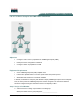
Lab 5.1.9 Configure Paging Groups Objective • Set up two paging groups. Each IP phone will be in a different paging group, and both paging groups will belong to yet another paging group. Equipment Requirements • Cisco CallManager Express (CME) capable router • Inline power capable switch or non-inline power switch with power injectors • Workstation with an Ethernet 10/100 NIC installed • Two Cisco IP phones • One analog phone This lab relies on labs 2.1.1, 2.1.2, 3.1.1, and 4.1.
• Configure one IP phone in the Sales paging group • Configure the other IP phone in the Technical Support paging group • Configure the emergency paging group to contain all sales and technical support phones • Test the paging feature • Configure all pages to use multicast Step 1 Configure paging groups a. Ensure that the two IP phones can call one another and that the analog phone can successfully dial either IP phone. Troubleshoot as necessary before proceeding.
m. The paging function allows you to dial a number and talk to a group of IP phones. In this scenario, the X500 (where X is the pod number) represents Sales, which could be a group of Sales representatives that have IP phones. The other paging function was assigned a number of X600 that represents Support. This could be the IT support staff. A helpdesk call could come in for the mail server and three administrators can manage the mail server.
k. From the privilege exec mode, use the command show running-config | begin telephonyservice command to view the changes. CMERouterX# show running-config | begin telephony-service l.
Answers to 5.1.9 Lab 1c. Equipment dependent 1g. Student dependent 1j. Student dependent 1n. Yes 2b. Student dependent 2d. Answers will vary depending on IOS, but one answer is 150. 2f. Student dependent 2l. Answers will vary based on the options chosen, but a sample configuration lists below: ephone-dn 7 number 1500 name Sales paging ! ephone-dn 8 number 1600 name Support paging ! ephone-dn 9 number 1700 name EmergencyAll paging ip 239.1.1.
mac-address 0013.C43B.4999 paging-dn 7 unicast button 1:1 2:3 ! ephone 2 username "KHampton" password cisco mac-address 000A.B7B1.33F5 speed-dial 1 1000 label “Alyssa” paging-dn 8 unicast type 7960 button 1:2 2:4 3:5 2o. Yes 116 - 165 IP Telephony v1.0 Lab 5.1.9 Copyright © 2005, Cisco Systems, Inc.
Lab 7.1.1 Configuring AutoQoS Objective • Enable the AutoQoS for VoIP feature on workgroup router interfaces Equipment Requirements • Two Cisco CallManager Express (CME) capable routers (each with a serial and PRI port configured) • Two inline power capable switches or non-inline power switches with power injectors • Adtran • Two IP phones This lab relies on labs 2.1.1, 2.1.2, 2.1.4, 3.1.1, 4.1.3, and 4.1.4 being successfully completed and loaded. In this lab ACME.
• Configure the command to implement AutoQoS for VoIP • Examine the results of implementing AutoQoS for VoIP Step 1 Verify Connectivity and IP Phones a. This lab requires that two pods be used and both pods are functional. Ensure that an IP phone from one pod can call an IP phone on the other pod. b. Does the phone call work from one pod to the other? If not, perform appropriate troubleshooting. __________ c. Have one pod partner slowly count from one to 10 while one or two phone connections are made.
Target IP address: Repeat count [5]: 1000 Datagram size [100]: 15000 Timeout in seconds [2]: Extended commands [n]: While the ping is occurring, place at least one phone call from one pod to another. Multiple calls can be made. Have one pod partner slowly count from one to 10 while the phone connection is active. d. How is the voice quality? ______________________________________________________ e.
policy-map AutoQoS-Policy-UnTrust class AutoQoS-VoIP-RTP-UnTrust priority percent 70 set dscp ef class AutoQoS-VoIP-Control-UnTrust bandwidth percent 5 set dscp af31 class AutoQoS-VoIP-Remark set dscp default class class-default fair-queue interface Serial0/1/0 ip address 10.19.0.2 255.255.255.
Answers to 7.1.1 Lab 1b. Yes 1d. Student’s opinion 1f. Student’s opinion 2d. Student’s opinion 2f. CEF implements expedited IP look-up and forwarding algorithm to deliver maximum Layer 3 switching performance. 2h. The serial link went down. 2l. Student’s opinion 2m. It improves the quality, but it is “best guess.” AutoQoS cannot know your company’s policies or bandwidth requirements for the type of data that your company (these two routers) uses. 121 - 165 IP Telephony v1.0 Lab 7.1.
Case Study 1: Registering IP Phones with a remote Call Manager Objectives • Place calls from IP Phones under R1 to IP Phones under R2 • Place calls from any IP Phone (under R1 and under R2) to the regular PSTN/POTS Phone • Place calls from the regular PSTN/POTS phone to IP Phones. Scenario The ACME Inc. has a new office at another city. In order to save money, a VoIP environment will be implemented by you. The CME Router will be located at the company’s main office.
Equipment Requirements 2 2811/2621XM; 2 Cisco IP Phones; 1 Regular Phone; 1 ADTRAN Atlas550 with a PSTN and PRI/T1 card; 2 Cisco Vlan Capable Switches; 123 - 165 IP Telephony v1.0 Case Study 1: Copyright © 2005, Cisco Systems, Inc.
1 1MFT-T1 card 1 NM-HDV Network Module; Appropriated cables and power supplies, Notes: - If using switch modules connected to the routers instead external 3550/3560 switches, check the “IPTX Appendix A - Using Switch Modules on the CME Routers” document.
headed to the PC will be be untagged (PC’s do not support tagged packets). Finally, configure the port connected to the Router as a trunk port.
Step 3 Voice CME Router Configuration 3.1 Preparing the Routers to handle the VLANs Create and configure two sub-interfaces on the fastEthernet 0/0 of R1 and two sub-interfaces on the fastEthernet 0/0 of R2. They will be used by the VLANs configured on the switch. On R1: R1(config)# int fa0/0 R1(config-if)# no ip address R1(config-if)# no shutdown R1(config)# R1(config)# R1(config)# R1(config)# int fa0/0.10 encapsulation dot1q 10 ip address 10.10.0.1 255.255.255.
On R2: R2(config)# ip dhcp pool DATA R2(dhcp-config)# network 10.20.0.0 255.255.255.0 R2(dhcp-config)# default-router 10.20.0.1 R2(config)# ip dhcp pool VOICE R2(dhcp-config)# network 10.25.0.0 255.255.255.0 R2(dhcp-config)# default-router 10.25.0.1 R2(dhcp-config)# option 150 ip 10.25.0.1 To exclude the routers ip address from the pool: On R1: R1(config)# ip dhcp excluded-address 10.10.0.1 R1(config)# ip dhcp excluded-address 10.15.0.1 On R2: R2(config)# ip dhcp excluded-address 10.20.0.
The ip source-address command specifies the address and port used by the CME software. Create the phones configuration files on the flash memory by issuing the create cnf-files. Specify the format of the dial plan to be used on internal IP Phones using the dialplanpattern command. Finally, the secondary-dialtone 9 command sets the 9 digit as the indicator for another dial-tone. It is used to make an off network call(get an outside line)..
R1(config)# ephone 1 R1(config-ephone)# mac-address xxxx.xxxx.xxxx R1(config-ephone)# type 7960 R1(config-ephone)# button 1:1 R1(config)# ephone 2 R1(config-ephone)# mac-address yyyy.yyyy.yyyy R1(config-ephone)# type 7940 R1(config-ephone)# button 1:2 Note: If you have more IP Phones, just add more ephone and ephone-dn block of commands. 3.5 Configuring the PSTN/POTS interface on the CME Router The PSTN/POTS cloud is being simulated by the ADTRAN Atlas550.
Note: The ADTRAN Atlas550 must be configured to forward calls to the PRI ports every time a 5555xxx number is dialed. Also, make sure you connected the CME Router’s PRI port to the right ADTRAN Atlas550 PRI port R1(config)# voice translation-rule 1 R1(cfg-translation-rule)# rule 1 /^555\(.+\)/ /\1/ R1(config)#voice translation-profile DID R1(cfg-translation-profile)# translate called 1 R2 doesn’t have PRI/T1 connection to the POTS/PSTN. There is no need to issue commands on R2.
The port command specifies which voice port will be used by the router to forward the calls to PSTN. Use the forward-digits command to specify how many digits, of the dialed number, will be forwarded, from left to the right. In this case, we are forwarding just the PSTN 7 digits, excluding the 9 used to gain the secondary dial tone. The port command specifies the voice-port used to forward/receive calls. In order to issue this command, you must choose the right voice-port to use.
Finally, connect a regular phone to the port 8 of the PSTN/POTS Module on ADTRAN Atlas550. The Atlas550 is configured to use the 555-600[1-8] numbers on the ports 1-8 of the PSTN/ POTS module. Connecting a regular phone to the port 8 of the PSTN/ POTS on Atlas550 makes this phone reachable by the number 555-6008. This regular phone is used to simulate a regular phone located at somewhere else in world. Step 5: Testing and Troubleshooting This scenario is simulating a real world situation.
r1#sh isdn status Global ISDN Switchtype = primary-ni ISDN Serial1/0/0:23 interface dsl 0, interface ISDN Switchtype = primary-ni Layer 1 Status: ACTIVE Layer 2 Status: TEI = 0, Ces = 1, SAPI = 0, State = MULTIPLE_FRAME_ESTABLISHED Layer 3 Status: 0 Active Layer 3 Call(s) Active dsl 0 CCBs = 0 The Free Channel Mask: 0x807FFFFF Number of L2 Discards = 0, L2 Session ID = 5 Total Allocated ISDN CCBs = 0 Another useful command is the debug ephone register.
no ip ips deny-action ips-interface ! no ftp-server write-enable ! interface FastEthernet0/0 no ip address shutdown duplex auto speed auto ! interface FastEthernet0/1 no ip address shutdown duplex auto speed auto ! interface Serial0/2/0 ip address 192.168.0.1 255.255.255.0 clockrate 56000 no shutdown ! interface Serial0/2/1 no ip address shutdown clockrate 2000000 ! router eigrp 1 network 192.168.0.
boot-start-marker boot-end-marker ! enable secret 5 $1$E70n$H.Rezw/Yhb4EAJVbIrmHa1 ! no aaa new-model ! resource policy ! no network-clock-participate slot 1 voice-card 1 dspfarm ! ip subnet-zero ! ! ip cef no ip dhcp use vrf connected ! no ip domain lookup no ip ips deny-action ips-interface ! no ftp-server write-enable ! interface FastEthernet0/0 no ip address shutdown duplex auto speed auto ! interface FastEthernet0/1 no ip address shutdown duplex auto speed auto ! interface Serial0/2/0 ip address 192.
line vty 0 4 password cisco login ! scheduler allocate 20000 1000 ! end 136 - 165 IP Telephony v1.0 Case Study 1: Copyright © 2005, Cisco Systems, Inc.
- 165 IP Telephony v1.0 Case Study 1: Copyright © 2005, Cisco Systems, Inc.
Case Study 2: Registering IP Phones with a local CME and forwarding calls to a remote Call Manager Objectives • Place calls from IP Phones under R1 to IP Phones under R2 • Place calls from any IP Phone (under R1 and under R2) to the regular PSTN/POTS Phone • Place calls from the regular PSTN/POTS phone to IP Phones. Scenario The ACME Inc. has a new office in another city. In order to save money, a VoIP environment will be implemented by you.
R1 has IP Phones under it to and must be able to forward the calls from these IP Phones to R2’s IP Phones. R2 must be able to forward calls to POTS/PSTN and calls to R1’s IP Phones as well.
Switch1(vlan)# vlan 10 name DATA state active Switch1(vlan)# vlan 15 name VOICE state active Switch1(vlan)# exit i. Configure the switch ports where the IP Phones will be connected. Despite the fact that the IP Phones do work with access mode ports, Cisco recommends that you configure the switch ports, connected to the IP Phones, as trunk ports. This way, it is possible to connect a PC on the IP Phone’s PC Port (this port is present in most of the Cisco IP Phones).
Step 2 Basic CME Router Configuration o. In this lab, you will be working with two routers. Connect to their console port and power them on. If the routers have a configuration already on it, erase the router and reload it. p. Enter privilege exec mode. q. Configure the hostname, passwords, interfaces, console and telnet access, eigrp routing protocol like the figure and make sure that both routers can reach each other. Use the ping command to troubleshoot, if necessary.
The PCs and IP Phones will need IP Addresses. Configure the DHCP Pools on both R1 and R2 routers so the routers will be able to teach IP information to PCs and IP Phones. On R1: R1(config)# ip dhcp pool DATA R1(dhcp-config)# network 10.10.0.0 255.255.255.0 R1(dhcp-config)# default-router 10.10.0.1 R1(config)# ip dhcp pool VOICE R1(dhcp-config)# network 10.15.0.0 255.255.255.0 R1(dhcp-config)# default-router 10.15.0.1 R1(dhcp-config)# option 150 ip 10.15.0.
3.3 Configuring the Telephony Service on the CME Router On this scenario, R1 and R2 will be running the Cisco CME Software. The IP Phones connected at R1 will register on R1 and the IP Phones connected to R2 will register on R2. The first step it to enable the CME software on R1/R2. Use the telephony-service to enable the CME and enter the telephony configure mode. Note: You can use the telephony-service setup command to start a “configuration script” but it will not be used here.
You will need to setup the ephone-dn’s and ephones on R1 in order for the voice service to work. From the configuration mode, create the ephone-dn’s. The ephone-dn command is used to create the ephone-dn. number, description and name will be use to specify the phone number of this ephone-dn, set a description to this ephone-dn and a name, respectively.
R2(config-ephone-dn)# name George R2(config)# ephone-dn 2 dual-line R2(config-ephone-dn)# number 5022 R2(config-ephone-dn)# description MrSpacely's Phone R2(config-ephone-dn)# name MrSpacely R2(config)# ephone 1 R2(config-ephone)# mac-address uuuu.uuuu.uuuu R2(config-ephone)# type 7960 R2(config-ephone)# button 1:1 R2(config)# ephone 2 R2(config-ephone)# mac-address vvvv.vvvv.
R1 will receive calls from the POTS system, so it is necessary to make it handle these calls. In the real world the dial plan used is E.64 but here we have created our own dial plan and configured it on the Atlas550. The Atlas550 is configured to forward calls with 555-5xxx numbering destination to the PRI ports. Use the voice translation-rule, voice translation-profile, translate called and rule commands to setup a translation. In this scenario, the inside IP Phones and regular phones have 5xxx numbering.
need 2 dial-peers: one pots dial-peer type (will handle POTS/PSTN calls) and one voip dialpeer type (will handle the calls between R1 and R2). R1 must to be able to forward/receive calls to/from the POTS system and forward/receive calls to/from other IP Phones (registered at R1 and registered at R2) or internal regular phones as well (if using an FXS card on R1/R2, see IPTX Case Study Appendix-B).
Some small but important changes must be made on R2 commands. It is necessary to change the dial-peer type. On R1 the pots dial-peer type was used but since R2 has no direct connection to the PSTN/POTS, all calls from R2, heading phones outside from R2 have to pass through R1, only a voip dial-peer type will be necessary. Create 2 voip dial-peers type: one to handle calls to PSTN/POTS and another to handle calls to R1’s IP Phones.
the PSTN/ POTS module. Connecting a regular phone to the port 8 of the PSTN/ POTS on Atlas550 makes this phone reachable by the number 555-6008. This regular phone is used to simulate a regular phone located at somewhere else in world. Step 5: Testing and Troubleshooting R1 and R2 are CME capable routers. R1 is located at the main office and R2 is located at the remote office. The phones under R1 will register at R1 and the phones under R2 must register at R2.
Total Allocated ISDN CCBs = 0 Another useful command is the debug ephone register. This command allows you to track the e-phones register process. Disconnect on of the IP Phones. Issue the debug ephone register and then connect the IP Phone again. Take a look on the debug messages on the R1 console. The show running-config, show ip interface brief, show ip route, show ip protocols are very useful and powerful troubleshoot commands as well. Below are the basic configuration files for R1 and R2.
! interface Serial0/2/0 ip address 192.168.0.1 255.255.255.0 clockrate 56000 no shutdown ! interface Serial0/2/1 no ip address shutdown clockrate 2000000 ! router eigrp 1 network 192.168.0.0 no auto-summary ! ip classless ! ip http server no ip http secure-server ! control-plane ! ! line con 0 logging synchronous line aux 0 line vty 0 4 password cisco login ! scheduler allocate 20000 1000 ! end Basic R2 configuration file: version 12.
no ip dhcp use vrf connected ! no ip domain lookup no ip ips deny-action ips-interface ! no ftp-server write-enable ! interface FastEthernet0/0 no ip address shutdown duplex auto speed auto ! interface FastEthernet0/1 no ip address shutdown duplex auto speed auto ! interface Serial0/2/0 ip address 192.168.0.2 255.255.255.0 clockrate 56000 no shutdown ! interface Serial0/2/1 no ip address shutdown clockrate 2000000 ! router eigrp 1 network 192.168.0.
Student Name____________________________________________ Course/Class______________________ Date__________________ IP Telephony v1.0 Student Skills Based Assessment (SBA) Version 1 Topology The ACME.com Company is transitioning from a traditional PBX to an IP based PBX using Cisco’s CallManager Express.
1. Configure the router and switch network using a workable IP addressing scheme for data, voice and management networks. 2. Install and configure CallManager Express on the router. 3. Configure two Cisco IP telephony phones with numbers (904) 555-5000 and (904) 5555001. 4. Configure a destination pattern on the routers FXS port to 555-5028. 5. Configure the GUI system administrator interface. 6. Configure the CallManager to display the DID number on the IP phones. 7.
Student Name____________________________________________ Course/Class______________________ Date__________________ IP Telephony v1.0 Student Skills Based Assessment (SBA) Version 2 Topology The ACME.com Company is transitioning from a traditional PBX to an IP based PBX using Cisco’s CallManager Express.
11. Configure two Cisco IP telephony phones. 12. Configure the CallManager to display the company name (Acme) on the IP phone. 13. Configure the CallManager to display a label for each IP phone number. 14. The customer also wants the paging feature enabled. 15. Configure the router’s T1 to connect to the Adtran’s T1 interface card. 16. Using the T1 interfaces, each IP Phone can call the first OCTAL port on the Adtran which has the number 555-6001. All tasks must be successfully completed.
Table 1 IP Telephony Addressing Scheme Pod Hostname of Cisco CME router or Switch CMERouter1 Pod 1 CMESwitch1 CMERouter2 Pod 2 CMESwitch2 CMERouter3 Pod 3 CMESwitch3 CMERouter4 Pod 4 CMESwitch4 IP Address on Ethernet Interface Type DHCP Pool Exclusion IP Network for DHCP Pool Default Router 10.10.0.1 /24 Data 10.10.0.110.10.0.10 10.10.0.0/24 10.10.0.1 10.15.0.1/24 Voice 10.15.0.110.15.0.10 10.15.0.0/24 10.15.0.1 10.1.0.1/24 Mgmt 10.1.0.4/24 Mgmt 10.20.0.1 /24 Data 10.20.0.110.
Table 2 IP Telephony Dial Plan Pod Dial Plan – Extension Numbers Voicemail Extension First E.164 DID number Router FXS Port 0 Router FXS Port 1 Pod 1 5000-5029 5555028 5105555000 5555028 5555029 Pod 2 5030-5059 5555058 5105555030 5555058 5555059 Pod 3 5060-5089 5555088 5105555060 5555088 5555089 Pod 4 5100-5129 5555128 5105555100 5555128 5555129 Pod 5 5130-5159 5555158 5105555130 5555158 5555159 158 - 165 IP Telephony v1.0 Table 2 Copyright © 2005, Cisco Systems, Inc.
TCP and UDP Port Numbers This document lists real important TCP/UDP port numbers related to voice QoS. TCP or UDP Port Number Purpose TCP 2000 to 2002 Skinny (CM Encore) TCP 11000 to 11999 H.323/H.245 Standard Connect ports TCP 1720 H.323/H.245 Fast Connect or H.323/H.225 ports TCP 1719 H.323/H.
Protocol Remote Source Port CallManager Destination Port OSI (DAP, DSP, DISP) TCP or UDP 120 NTP UDP 123 WINS UDP 137-139 SNMP UDP 161 CallManager Source Port Remote Device Destination Port Remote Devices Notes DCD Directory SNMP Trap WINS Server Windows Internet Name Service Directory Services When integrated with Corporate Directory UDP 162 LDAP TCP 389 TCP 389 HTTPS / SSL TCP 443 SMB TCP 445 TCP 445 Syslog TCP 514 UDP 514 RMI TCP 10991129 MS SQL TCP 1433 TCP 1433 H.
Protocol Remote Source Port CallManager Destination Port H.323 H.245 TCP 1100065535 SCCP TCP 2000 Skinny Gateway (Analogue) Skinny Gateway (Digital) CallManager Source Port MGCP Backhaul TCP 2428 RTS Serv Cisco Extended Service Cisco Extended Service RIS Data Collector RIS Data Collector Digital Skinny Gateway TCP 2002 UDP 2427 Remote Devices IOS H.323 Gateways.
Protocol Remote Source Port CallManager Destination Port SCCP TCP 3224 MS Terminal Services TCP 3389 CallManager Source Port Entercept HID Agent CallManager SIP VNC http helper Remote Device Destination Port TCP 5000 TCP/UDP 5060 TCP 5060 Remote Devices Notes Media Resources Conference Bridges / Xcoders Windows Terminal Services Host Intrusion Detection Console SIP Trunk Default Port TCP 580x Can use TCP 1024 - 65535 Remote Control TCP 690x Virtual Network Computer Display Remote Contro
Protocol Remote Source Port DC Directory CallManager Destination Port CallManager Source Port Remote Device Destination Port TCP 8404 Remote Devices Notes Embedded Directory Services Used for Directory services. Application Authentication / configuration. SoftPhone Directory.
Adtran Atlas 550 Configurations 164 - 165 IP Telephony v1.0 Adtran Atlas 550 Configuration Copyright © 2005, Cisco Systems, Inc.
Command List: Command Example Description archive tar /xtract source destination auto assign 2 to 2 button 1:1 configure terminal copy source destination create cnf-files default-router 10.X0.0.1 enable enable password cisco ephone 1 ephone-dn 1 dual-line exit hostname name interface fa 0/0 ip address 10.X0.0.1 255.255.255.0 ip dhcp excluded-address 10.X0.0.1 10.X0.0.10 ip dhcp pool CMEX ip source-address 10.X0.0.1 port 2000 keepalive 10 line vty 0 4 load 7960-7940 P00303020214 login mac H.H.