CH A P T E R 7 Installing the IPS 4510 and IPS 4520 Contents This chapter describes the Cisco IPS 4510 and IPS 4520, and includes the following sections: • Installation Notes and Caveats, page 7-1 • Product Overview, page 7-2 • Chassis Features, page 7-3 • Specifications, page 7-9 • Accessories, page 7-10 • Memory Configurations, page 7-11 • Power Supply Module Requirements, page 7-11 • Supported SFP/SFP+ Modules, page 7-11 • Installing the IPS 4510 and IPS 4520, page 7-12 • Removing an
Chapter 7 Installing the IPS 4510 and IPS 4520 Product Overview Warning Only trained and qualified personnel should install, replace, or service this equipment. Statement 49 Caution Read the safety warnings in the Regulatory Compliance and Safety Information for the Cisco Intrusion Prevention System 4500 Series Sensor Appliance document and follow proper safety procedures when performing the steps in this guide.
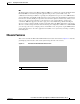
Chapter 7 Installing the IPS 4510 and IPS 4520 Chassis Features IME The Intrusion Prevention System Manager Express (IME) 7.2.3 and later also support the IPS 4510 and IPS 4520. IME is a network management application that provides system health, events, and collaboration monitoring in addition to reporting and configuration for up to ten sensors.
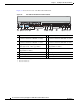
Chapter 7 Installing the IPS 4510 and IPS 4520 Chassis Features Figure 7-2 shows the front view of the IPS 4510 and IPS 4520.
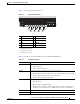
Chapter 7 Installing the IPS 4510 and IPS 4520 Chassis Features Figure 7-3 shows the front panel indicators. Figure 7-3 Front Panel Indicators 1 USB R PW OT BO 1 M AR AL T AC 3 N VP 1 PS 5 2 4 0 PS D1 HD 7 6 1 PWR 2 BOOT 3 ALARM 4 ACT1 5 VPN2 6 PS1 7 PS0 8 HDD13 D0 HD AUX CONSOLE 253904 0 9 8 9 HDD24 1. Not supported at this time. 2. Not supported at this time. 3. Not supported at this time. 4. Not supported at this time.
Chapter 7 Installing the IPS 4510 and IPS 4520 Chassis Features Table 7-1 Front Panel Indicators (continued) Indicator Description PS1 Indicates the state of the power supply module installed on the right when facing the back panel: PS0 HDD1 HDD2 • Off—No power supply module present or no AC input. • Green—Power supply module present, on, and good. • Amber—Power or fan module off or failed.
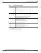
Chapter 7 Installing the IPS 4510 and IPS 4520 Chassis Features Figure 7-4 shows the back panel features. Figure 7-4 Back Panel Features 3 1 2 7 4 6 Cisco-ASA-FAN O FA UT IL F O AN K 100-240V 15.0/8.0.
Chapter 7 Installing the IPS 4510 and IPS 4520 Chassis Features Table 7-2 describes the power supply module and fan module indicators. Table 7-2 Power Supply Module and Fan Module Indicators Indicator Description IN OK Indicates status of power supply module: FAN OK • Off—No AC power cord connected or AC power switch off. • Green—AC power cord connected and AC power switch on. Indicates status of fan module OUT FAIL • Off—Fan module failure or AC power switch off.
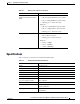
Chapter 7 Installing the IPS 4510 and IPS 4520 Specifications Table 7-3 Ethernet Port Indicators (continued) Indicator Description 10-Gigabit Ethernet Fiber (SFP+)/1-Gigabit Ethernet Fiber (SFP) • Left side: – Off—No 10-Gigabit Ethernet physical link – Green—10-Gigabit Ethernet physical link – Flashing green1—Network activity • Right side: – Off—No 1-Gigabit Ethernet physical link – Green—1-Gigabit Ethernet physical link – Flashing green1—Network activity Management port • Left side: – Green—Ph
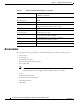
Chapter 7 Installing the IPS 4510 and IPS 4520 Accessories Table 7-4 IPS 4510 and IPS 4520 Specifications (continued) Maximum heat dissipation 3960 BTU/hr (100 VAC) 5450 BTU/hr (200 VAC) Power supply output steady state 1200W Maximum peak 1200W Environment Temperature Operating 32°F to 104°F (0°C to 40°C) Nonoperating -40°F to 158°F (-40°C to 70°C) Airflow Front to back Relative humidity (noncondensing) Operating 10% to 90% Nonoperating 5% to 95% Altitude Operating 0 to 3000 ft (9843 ft) Non
Chapter 7 Installing the IPS 4510 and IPS 4520 Memory Configurations Memory Configurations The IPS 4510 and IPS 4520 have up to 6 DIMM modules per CPU. DIMM population is platform-dependent. Table 7-5 shows the memory configurations. Table 7-5 Memory Configurations Model Memory IPS 4510 24-GB DRAM IPS 4520 48-GB DRAM Power Supply Module Requirements Table 7-6 lists the power supply module requirements. Table 7-6 Power Supply Module Requirements 50 V 12 V 3.3 V_STBY Maximum 52.0 V 12.2.
Chapter 7 Installing the IPS 4510 and IPS 4520 Installing the IPS 4510 and IPS 4520 Table 7-7 lists the SFP/SFP+ modules that the IPS 4510 and IPS 4520 support.
Chapter 7 Installing the IPS 4510 and IPS 4520 Installing the IPS 4510 and IPS 4520 Connect one RJ-45 connector to the Management 0/0 interface. 7 6 5 4 3 2 1 0 0 1 MGMT 0 1 USB c. 253908 b. Connect the other end of the Ethernet cable to the Ethernet port on your computer or to your management network. Caution Management and console ports are privileged administrative ports. Connecting them to an untrusted network can create security concerns.
Chapter 7 Installing the IPS 4510 and IPS 4520 Installing the IPS 4510 and IPS 4520 Connect one end of the LC cable to the SFP/SFP+ module. 9 8 7 6 253907 b. SFP/SFP + c. Step 5 Connect the other end of the LC cable to a network device, such as a router or switch. Install the electrical cables. a. Attach the power cable to the power supply module on the back of the sensor. Cisco AS A 1200W AC Cisco-A SA Cisco AS -FAN A 1200W AC IN K FAN UT O OK O AIL 253972 100-240 V 15.0/8.0 .
Chapter 7 Installing the IPS 4510 and IPS 4520 Removing and Installing the Core IPS SSP Step 6 Power on the sensor. Caution If the appliance is subjected to environmental overheating, it shuts down and you must manually power cycle it to turn it on again. Step 7 Check the PWR indicator on the front panel of the sensor to verify power socket connectivity. It should be green. To verify power supply operation, check the PS0 and PS1 indicators on the front panel. They should be green.
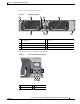
Chapter 7 Installing the IPS 4510 and IPS 4520 Removing and Installing the Core IPS SSP Step 7 Grasp the ejection levers at the left and right bottom of the designated slot and pull them out. SFP31 SFP20 SFP17 SFP60 5 4 3 2 4520 331818 Cisco IPS 1 0 0 1 MGMT 0 USB 1 R PW 2 OT BO M AR AL T AC N VP 1 PS 0 PS D1 HD D0 HD AUX CONSOL E RESET 1 2 1 2 Module Ejection levers Step 8 Grasp the sides of the module and pull it all the way out of the chassis.
Chapter 7 Installing the IPS 4510 and IPS 4520 Removing and Installing the Power Supply Module Removing and Installing the Power Supply Module The IPS 4510 ships with one power supply module and one fan module installed, and the IPS 4520 ships with two power supply modules installed in a load balancing/sharing configuration. This configuration ensures that if one power supply module fails, the other power supply module assumes the full load until the failed power supply module is replaced.
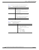
Chapter 7 Installing the IPS 4510 and IPS 4520 Removing and Installing the Power Supply Module Step 5 Install the new power supply module by aligning it with the power supply module bay and pushing it into place until it is seated. 2 Cisco AS A 1200W AC Cisco-A SA 253971 Cisco AS -FAN A 1200W AC 100-240V IN K 15.0/8.0. A O 56/60Hz INP N FA K OUT IL O FA UT FAN OUTPUT 100-240V 15.0/8.0.
Chapter 7 Installing the IPS 4510 and IPS 4520 Removing and Installing the Fan Module Removing and Installing the Fan Module The IPS 4510 ships with one power supply module and one fan module installed, and the IPS 4520 ships with two power supply modules instead of a power supply module and a fan module. You can replace the fan module in the IPS 4510 if necessary. The fan module is hot-pluggable.
Chapter 7 Installing the IPS 4510 and IPS 4520 Installing the Slide Rail Kit Hardware Step 3 Install the new fan module by aligning it with the fan module bay and pushing it into place until it is seated. 2 Cisco AS A 1200W AC Ci Cisc sco-A o-ASA SA-FA -FANN 100-240 V 15.0/8.0 .A 56/60Hz 253910 IN K FAN UT O OK O FAIL 3 1 2 1 Fan module and fan handle 3 Power supply module 2 Fan module screw Step 4 Tighten the captive screws.
Chapter 7 Installing the IPS 4510 and IPS 4520 Installing and Removing the Slide Rail Kit Figure 7-6 shows all of the brackets that can be removed for the fixed rack mount.
Chapter 7 Installing the IPS 4510 and IPS 4520 Installing and Removing the Slide Rail Kit Package Contents The slide rail kit package contains the following items: • Left and right slide rails • Six #10-32 screws • Two #10-32 cage nuts Installing the Chassis in the Rack To install the chassis in the rack using the slide rail kit, follow these steps: Step 1 Press the latch on the end of the slide rail and push forward to engage the pins in the rack until the clip clicks and locks around the rack po
Chapter 7 Installing the IPS 4510 and IPS 4520 Installing and Removing the Slide Rail Kit For square hole posts, square studs must be attached fully inside the square hole on the rack rail. For threaded hole posts, the round stud must fully enter inside the threaded hole rack rail (Figure 7-9). Note After installing the square or round studs into the rack post, verify that the locking clip is fully seated and secure against the rack rail.
Chapter 7 Installing the IPS 4510 and IPS 4520 Installing and Removing the Slide Rail Kit Step 2 Caution Secure the slide rail to the rack post with the provided #10-32 screws by tightening the screws at the front and rear end of the slide rail to the rack post (Figure 7-10). Both front and rear rack posts must be secured with the screws before you install the chassis. It is critical that the screws are installed and secured to the front and rear end of the slide rails.
Chapter 7 Installing the IPS 4510 and IPS 4520 Installing and Removing the Slide Rail Kit Step 3 For square hole racks, install one #10-32 cage nut on each side of the rack rail (Figure 7-11). Leave one square hole spacing above the slide rail. The cage nut will be used later to secure the chassis to the rack post. For threaded hole racks, no additional hardware is needed.
Chapter 7 Installing the IPS 4510 and IPS 4520 Installing and Removing the Slide Rail Kit Step 4 Install the chassis on the outer rail. Make sure that the U-bars are aligned to the outer rail evenly, then push the chassis into the rack (Figure 7-12). Caution Before installing the chassis, make sure that the slide rails are properly installed and that the perforated holes on the outer slide rail align with the perforated holes on the chassis.
Chapter 7 Installing the IPS 4510 and IPS 4520 Installing and Removing the Slide Rail Kit Step 5 Tighten the screws to secure the chassis to the rack (Figure 7-13). Use the upper hole to secure the chassis to the rack. a. For square hole racks, secure the chassis to the rack by installing the #10-32 screw into the cage nut that you installed in Step 3. b. For threaded hole racks, secure the front of the chassis by installing the #10-32 screws into the rack threaded hole.
Chapter 7 Installing the IPS 4510 and IPS 4520 Installing and Removing the Slide Rail Kit Removing the Chassis from the Rack To remove the chassis from the rack, follow these steps: Step 1 Remove the screws from the front brackets of the rail post (Figure 7-14). Removing the Screws from the Outer Rail 330599 Figure 7-14 Step 2 Pull out the chassis to the locked position. Cisco Intrusion Prevention System Appliance and Module Installation Guide for IPS 7.
Chapter 7 Installing the IPS 4510 and IPS 4520 Installing and Removing the Slide Rail Kit Step 3 Press down the release hook to remove the chassis from the rack (Figure 7-15). Pressing Down the Release Hook 330564 Figure 7-15 Cisco Intrusion Prevention System Appliance and Module Installation Guide for IPS 7.
Chapter 7 Installing the IPS 4510 and IPS 4520 Rack-Mounting the Chassis Using the Fixed Rack Mount Step 4 Remove the two screws from the front and rear of the rack that are securing the slide rail, and release the latch and pull out the rails (Figure 7-16). Releasing the Latch to Pull Out the Rails 330565 Figure 7-16 Rack-Mounting the Chassis Using the Fixed Rack Mount If you are not able to use the slide rail kit in your rack installation, an optional fixed rack mount solution is available.
Chapter 7 Installing the IPS 4510 and IPS 4520 Rack-Mounting the Chassis Using the Fixed Rack Mount Position the front bracket on the side of the sensor and line up the bracket screws with the screw holes on the sensor.
Chapter 7 Installing the IPS 4510 and IPS 4520 Rack-Mounting the Chassis Using the Fixed Rack Mount (Optional) Install the proper slide-mount brackets on to the rear bracket on the chassis.
Chapter 7 Installing the IPS 4510 and IPS 4520 Installing the Cable Management Brackets Installing the Cable Management Brackets The IPS 4510 and IPS 4520 ship with two cable management brackets that you can use to organize the cables connected to the sensor. To install the cable management brackets on the sensor, follow these steps: Step 1 Power off the sensor. Step 2 Remove the power cable from the sensor.
Chapter 7 Installing the IPS 4510 and IPS 4520 Troubleshooting Loose Connections Cable Management Brackets for the Slide Rail 333053 Figure 7-18 Step 4 Tighten the screws in to the rack. Step 5 Reattach the power cable to the sensor. Step 6 Organize the cables through the cable management brackets on the sensor. Step 7 Power on the sensor.
Chapter 7 Installing the IPS 4510 and IPS 4520 IPS 4500 Series Sensors and the SwitchApp IPS 4500 Series Sensors and the SwitchApp The 4500 series sensors have a built in switch that provides the external monitoring interfaces of the sensor. The SwitchApp is part of the IPS 4500 series design that enables the InterfaceApp and sensor initialization scripts to communicate and control the switch. Any application that needs to get or set information on the switch must communicate with the SwitchApp.
Chapter 7 Installing the IPS 4510 and IPS 4520 IPS 4500 Series Sensors and the SwitchApp Cisco Intrusion Prevention System Appliance and Module Installation Guide for IPS 7.