
User's Manual


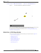

Table Of Contents
- Contents
- Preface
- Overview
- Installation
- Preparing for Installation
- Unpacking the Components
- Installation Guidelines
- Installing the Devices
- Connecting the Protective Ground and Power
- Wiring the Alarm Circuits
- Connecting to Device Ports

Ta b le 1-1 WPAN Gateway Models
Model Description
IR509U-WP-915/K9 The IR509U-WP-915/K9 model includes:
• IEEE 802.15.4g/e WPAN 902-928 MHz mesh interface
• 10/100 Fast Ethernet port
• RS232 serial port
• RS232/RS485 serial port
• USB port
• Configurable alarm input (normally open or normally closed setup)
• IP30 enclosure
29/OCT/2014 REVIEW DRAFT — CISCO CONFIDENTIAL
1-3
Cisco IR500 Series WPAN Gateway and Range Extender Installation and Configuration Guide
Chapter 1 Overview
Assembly Details
WPAN Range Extender Models
Table 1-2 lists and describes the WPAN range extender models.
Ta b le 1-2 WPAN Range Extender Models
Model Description
IR529-WP-915S/K9 Connected Grid Basic Range Extender—IEEE 802.15.4e/g WPAN
900 MHz
IR529-UBWP-915
S/K9 Connected Grid Advanced Range Extender, configurable with single
ant
enna and b
attery backup support—IEEE 802.15.4e/g WPAN 900 MHz
IR529-UBWP-915D/K9 Connected Grid Advanced Range Extender
, configurable w
ith dual antenna
and battery backup support—IEEE 802.15.4e/g WPAN 900 MHz
IR529-UWP-915D/K9 Connected Grid Advanced Range Extender, configurable with dual
antenna—IEEE 802.15.4e/g WP
AN 900 MHz
Assembly Details
• Front Panel—WPAN Gateway, page 1-3
• Rear Panel—WPAN Gateway, page 1-6
• Bottom Panel—WPAN Range Extender, page 1-7
• Top Panel—WPAN Range Extender, page 1-11
Front Panel—WPAN Gateway
This section describes the front panel components shown in Figure 1-1:
• Status LEDS, page 1-4
• Antenna Connector, page 1-4
• RS232/RS485 DCE Port, page 1-5