
User's Manual


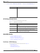


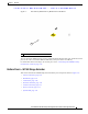

Table Of Contents
- Contents
- Preface
- Overview
- Installation
- Preparing for Installation
- Unpacking the Components
- Installation Guidelines
- Installing the Devices
- Connecting the Protective Ground and Power
- Wiring the Alarm Circuits
- Connecting to Device Ports

29/OCT/2014 REVIEW DRAFT — CISCO CONFIDENTIAL
1-4
Cisco IR500 Series WPAN Gateway and Range Extender Installation and Configuration Guide
Chapter 1 Overview
Assembly Details
• RS232 DTE Port, page 1-5
• USB Port, page 1-5
• 10/100 Fast Ethernet Port, page 1-5
• Power and Alarm Connector, page 1-5
• Reset Switch, page 1-6
Figure 1-1 Front Panel of WPAN Gateway IR509U-WP-915/K9 Model
1
2
3
4
6
7
8
390980
5
9
1 Status LEDs 6 10/100 Fast Ethernet port
2 Antenna connector 7 Power
1
1. DC power.
and alarm connector
3 RS232-DCE/RS485 selectable port 8 Reset button
4 RS232-DTE port 9 Ground connection point
5 USB port
Status LEDS
The status LEDs provide status information on the WPAN gateway status, activity, and performance. For
more information, see the “WPAN Gateway LEDs” section on page 1-12.
Antenna Connector
The antenna connector is a QMA, panel-mounted, 50-ohm connector for connecting the antenna to the
WPAN gateway.