
User's Manual


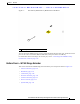

Table Of Contents
- Contents
- Preface
- Overview
- Installation
- Preparing for Installation
- Unpacking the Components
- Installation Guidelines
- Installing the Devices
- Connecting the Protective Ground and Power
- Wiring the Alarm Circuits
- Connecting to Device Ports

29/OCT/2014 REVIEW DRAFT — CISCO CONFIDENTIAL
1-5
Cisco IR500 Series WPAN Gateway and Range Extender Installation and Configuration Guide
Chapter 1 Overview
Assembly Details
RS232/RS485 DCE Port
The RS232/RS485 DCE port is a configurable serial port for connecting a serial device to the WPAN
Gateway. The Connected Grid Network Management System (CG-NMS) application is used to configure
the port.
The port can be configured for RS232 or RS485. RS232 operates in full duplex mode on the port, and
RS48
5 operat
es in half duplex or full duplex mode. You can also use the CG-NMS to obtain statistics
about the serial port including bytes sent and bytes received information.
For information about connecting to the RS232-DCE or RS485 port, see the “Connecting to the
RS232DCE/RS485 or RS232-DTE Ports” section on page 2-33.
RS232 DTE Port
The RS232 DTE port is a configurable serial port for connecting a serial device to the WPAN Gateway.
The Connected Grid Network Management System (CG-NMS) application is used to configure the port.
You can also use the CG-NMS to obtain st
atistics about the port including bytes sent and bytes received
information.
For information about connecting to the RS232 DTE port, see the “Conn
ecting to the RS232DCE/RS485
or RS232-DTE Ports” section on page 2-33.
USB Port
For information about the USB port, see the Cisco IR 500 Series WPAN Gateway and Range Extender
Release Notes on Cisco.com.
For information about connecting to the USB port, see the “Connecting to the USB Port” section on
page 2-35.
10/100 Fast Ethernet Port
The 10/100 Fast Ethernet port provides IPv4 connectivity to devices. Connectivity over the IPv6-based
Field Area Network (FAN) is provided using the Mapping of Address and Port using Translation
(MAP-T) protocol by the WPAN gateway.
For information about connecting to the Fast Ethernet 10/100 port, see the “Connecting to the 10/100
Fast Ethernet Port” section on page 2-34.
Power and Alarm Connector
You connect the DC power and alarm connections to the WPAN gateway through the front panel
connector. The gateway requires a DC power supply. The power connector labeling is on the connector.
Figure 1-2 shows the power and alarm connector.