
User's Manual

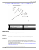
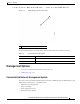

Table Of Contents
- Contents
- Preface
- Overview
- Installation
- Preparing for Installation
- Unpacking the Components
- Installation Guidelines
- Installing the Devices
- Connecting the Protective Ground and Power
- Wiring the Alarm Circuits
- Connecting to Device Ports

29/OCT/2014 REVIEW DRAFT — CISCO CONFIDENTIAL
1-10
Cisco IR500 Series WPAN Gateway and Range Extender Installation and Configuration Guide
Chapter 1 Overview
Assembly Details
Figure 1-6 Bottom Panel of Advanced Range Extender IR529-UBWP-915D/K9 and
IR529-UWP-915D/K9 Models
1
2
391360
3
4
3
5
6
7
8
1 Antenna connector 1—N-type (female) 5 Protective vent port
2 Antenna connector 2—N-type (female) 6 Ground connection
3 Hard points M8 x 1.25 mm, 8 mm deep
(5/
16-18 i
n., 5/16 in. deep)
7 Power
1
1. AC power.
connector
4 Console port 8 System LED
Antenna Connector
The antenna connector is a type N female coaxial connector.
Hard Points
The hard points are used for alternate mounting or as attach points for additional equipment.
Console Port
You can connect the WPAN range extender to a PC or laptop through the RJ-45 console port. The RJ-45
console port uses the Cisco Console Port RJ45-to-DB9 cable (Cisco part number 72-3383-01).
The console port is covered with a cable port seal—this is a liquid tight
cover for protecting the WPAN
range extender from environmental elements.
For information about connecting to the console port,
see the “Connecting to the WPAN Range Extender
Console Port” section on page 5-13.