
User's Manual

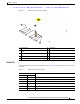
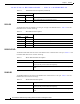
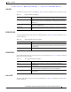
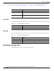

Table Of Contents
- Contents
- Preface
- Overview
- Installation
- Preparing for Installation
- Unpacking the Components
- Installation Guidelines
- Installing the Devices
- Connecting the Protective Ground and Power
- Wiring the Alarm Circuits
- Connecting to Device Ports

29/OCT/2014 REVIEW DRAFT — CISCO CONFIDENTIAL
1-15
Cisco IR500 Series WPAN Gateway and Range Extender Installation and Configuration Guide
Chapter 1 Overview
LEDs
USB LED
The USB Led shows the status of the USB port. Table 1-9 lists the USB LED Colors and their meanings.
Ta b le 1-9 USB LED Status Description
Color Description
Off USB is not selected as the active DA2 Port (Which means that
either the
RS232 is selected as the active DA2 Port or the DA2 port is turned off
completely)
Solid yellow USB is selected as the DA2 Port and is active, but does not detect any
USB de
vice plugged i
n yet.
Solid green USB port is active and has detected a
USB d
evice plugged in to its USB
Port
RS232-DTE LED
The RS232-DTE LED shows the status of the RS232-DTE port. Table 1-10 lists the USB LED Colors
and their meanings.
Ta b le 1-10 RS232-DTE LED Status Description
Color Description
Off RS232-DTE is not selected as the active DA2 Port (W
hich means that
either the USB is selected as the active DA2 Port or the DA2 port is turned
off completely).
Solid green RS232-DTE is selected as the DA2 Port and is active.
10/100 FE LED
The 10/100 FE LED shows the connectivity status of the 10/100 FE port. Table 1-11 lists the 10/100 FE
LED colors and their meanings.
Ta b le 1-11 10/100 FE LED Status Description
Color Description
Off 10/100 FE port is inactive—the port is powered off or nothing is
connected t
o it.
Green 10/100 FE port is active—a link is established with a connected device,
an
d communication i
s established and a speed is negotiated.
Blinking yellow Traffic activity detected—data communica
tion with a connecte
d device
is in progress.
Power LED
The Power LED shows the power status of the WPAN gateway. Table 1-12 lists the power LED colors
and their meanings.