
User's Manual


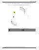
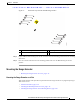
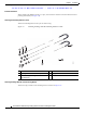


Table Of Contents
- Contents
- Preface
- Overview
- Installation
- Preparing for Installation
- Unpacking the Components
- Installation Guidelines
- Installing the Devices
- Connecting the Protective Ground and Power
- Wiring the Alarm Circuits
- Connecting to Device Ports

29/OCT/2014 REVIEW DRAFT — CISCO CONFIDENTIAL
2-18
Cisco IR500 Series WPAN Gateway and Range Extender Installation and Configuration Guide
Chapter 2 Installation
Connecting the Protective Ground and Power
Connecting the Protective Ground and Power
• Grounding the WPAN Gateway, page 2-18
• Wiring the WPAN Gateway DC Power, page 2-20
• Grounding the WPAN Range Extender, page 2-24
• Wiring the WPAN Range Extender AC Power, page 2-27
Grounding the WPAN Gateway
Make sure to follow any grounding requirements at your site.
Warning
This equipment must be grounded. Never defeat the ground conductor or operate the equipment in the
absence of a suitably installed ground conductor. Contact the appropriate electrical inspection
authority or an electrician if you are uncertain that suitable grounding is available.
Statement 1024
Warning
This equipment is intended to be grounded to comply with emission and immunity requirements.
Ensure that the switch functional ground lug is connected to earth ground during normal use.
Statement 1064
Caution To make sure that the equipment is reliably connected to earth ground, follow the grounding procedure
instructions, and use 14-to-16 AWG wire.
Caution Use at least a 4 mm
2
conductor to connect to the external grounding screw.
The ground lug (part number 32-204389=) for the WPAN gateway is supplied.
To ground the WPAN Gateway to earth ground by using the ground screw, follow these steps:
Step 1 Locate the ground screw (part number 48-1163-01=) in the WPAN gateway packaging kit. Store the
ground screw for later use.
Step 2 Use a wire stripping tool to strip the 14-to-16 AWG grounding wire to 0.22 in. (5.56 mm).
Step 3 Insert the ground wire into the ring terminal lug, and using a crimping tool, crimp the terminal to the
wire. See Figure 2-9.